
Industrial robot comprising a portable operating unit which a movable key device for identification of the robot

Inactive Publication Date: 2004-07-29
ABB (SCHWEIZ) AG
View PDF12 Cites 58 Cited by
  • Summary
  • Abstract
  • Description
  • Claims
  • Application Information

AI Technical Summary

Benefits of technology

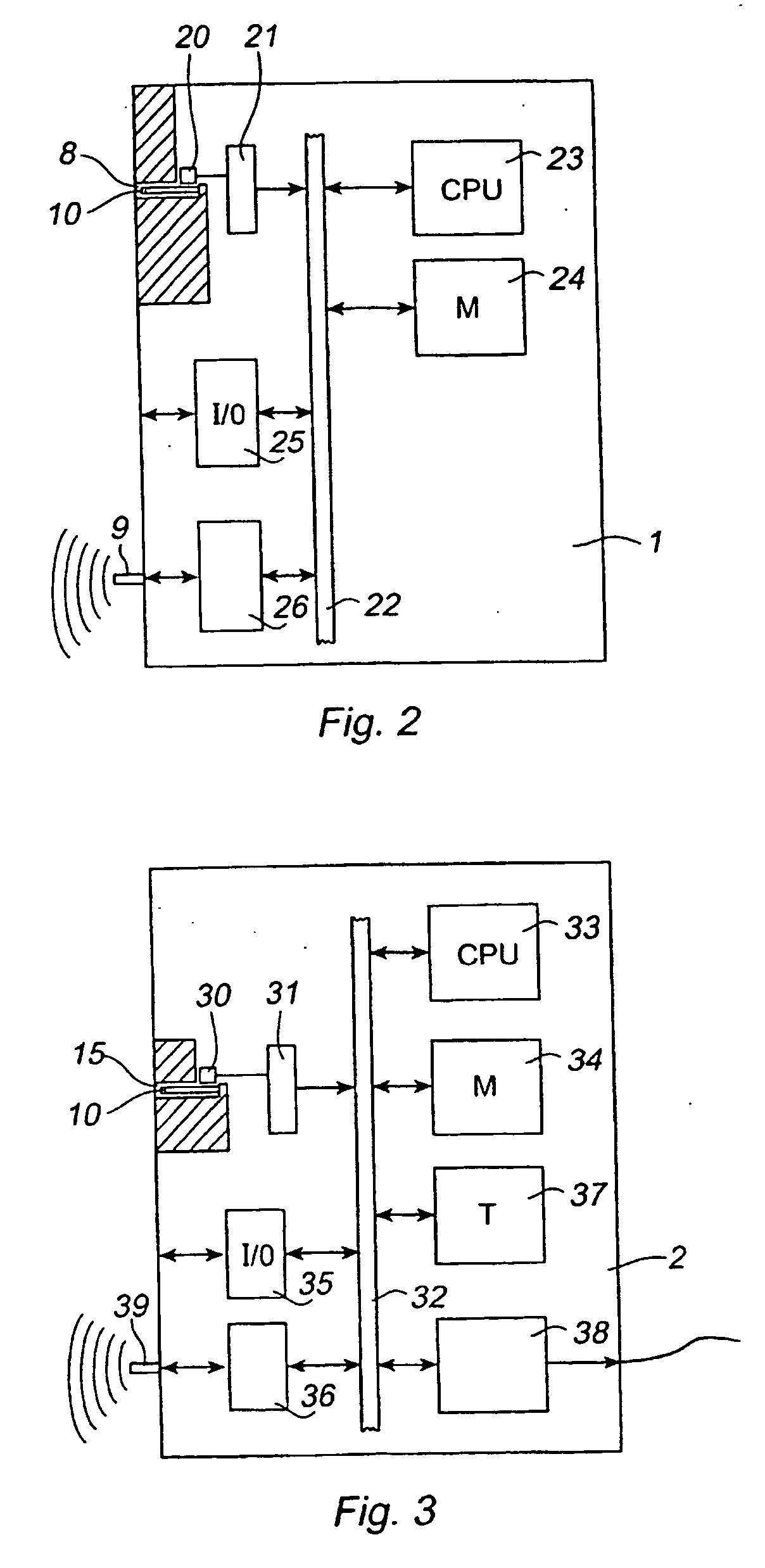
[0018] According to an embodiment of the invention, the robot comprises a second member for receiving the movable key device and said second receiving member being located at or in connection with the control unit of the robot. While the robot is not operated by the operating unit, the key device is returned to the robot, preferably to the controller or to a location close to the controller. Thus, it is easy for an operator to visually notice to which robot the key device belongs and mistakes due to the operator taking the wrong key device are prevented.

Problems solved by technology

There are many problems related to having a cable between the control unit and the teach pendant, particularly when there are several robots arranged near each other in a robot line.
The cable between the teach pendant and the control unit has to be rather long and the risk for twisting the cables of the robots is considerable.
Neighboring robots could also have their cables twisted with each other and thus it is sometimes difficult to know to which robot a certain teach pendant belongs.
There is also a risk for breakage of the cables resulting in loss of communication between the teach pendant and the control unit.
Otherwise, there is a risk for personal injury, should the operator believe that he is operating a certain robot but is instead operating another robot in the cell.
Thus, a problem arising when using a teach pendant not physically connected with the robot, is how to ensure that the correct robot is connected with the teach pendant.
Another problem with wireless communication between the robot and the teach pendant is the functioning of the emergency stop button on the teach pendant when the teach pendent is not connected with any robot.
A problem associated with having a movable key device is the risk for returning the key device to the wrong robot.

Method used


Image

  • Industrial robot comprising a portable operating unit which a movable key device for identification of the robot
  • Industrial robot comprising a portable operating unit which a movable key device for identification of the robot
  • Industrial robot comprising a portable operating unit which a movable key device for identification of the robot

Examples


Embodiment Construction

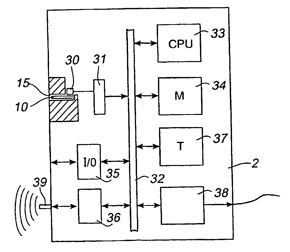
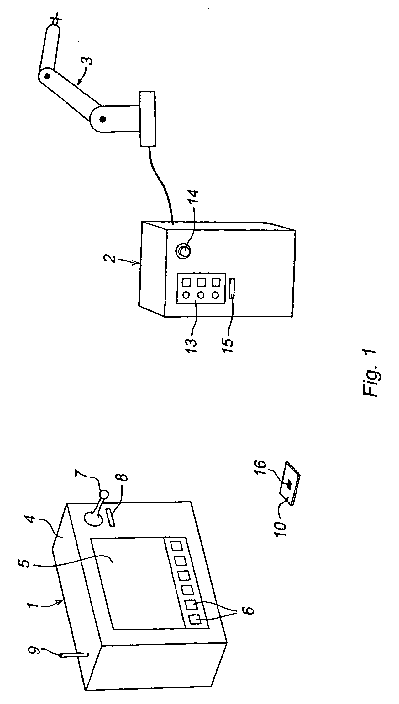
[0037] FIG. 1 shows an industrial robot according to the invention, comprising a portable operating unit 1 and a control unit 2 coupled for transmitting data via a communication cable or a link to a manipulator 3. The operating unit and the control unit are adapted for radio communication with each other. The control unit 2 is capable of processing and outputting data received from the operating unit. The operating unit 1 comprises a body 4, a display screen 5, a set of function keys 6, and a joystick 7. The function keys 6 permit an operator to select various states for the control system. The joystick is used for controlling the movement of the manipulator when the robot is manually operated and could be used as a mouse. The operating unit 1 further comprises an antenna 9 for radio communication with the control unit 2 and a slot 8 adapted for receiving a key device 10. In this embodiment of the invention the key device is a card having an electronic hardware device 16 including a...


PUM


Abstract

An industrial robot comprising a manipulator (3), a control unit (2) having means for automatically operating the manipulator, and a portable operating unit (1) having means for manually operating the manipulator. The robot further comprises a movable key device (10) carrying information about the identity of the robot and said portable operating unit (1) comprising a member (8) for receiving said movable key device and means for reading the robot identity from the key device.

Description

[0001] The present invention relates to an industrial robot comprising a manipulator, a control unit having means for automatically operating the manipulator, and a portable operating unit having means for manually operating the manipulator.[0002] The present invention also relates to an industrial robot system comprising a plurality of industrial robots each having a manipulator and a control unit having means for automatically operating the manipulator, and at least one portable operating unit for teaching and programming the manipulators, which portable operating unit is adapted for wireless communication with the control units.[0003] The present invention further relates to an operating unit for an industrial robot having a specified identity, a manipulator and a control unit for controlling the manipulator, the operating unit comprising means for manually operating the manipulator and means for communicating with the control unit.[0004] The present invention further relates to ...

Claims


Application Information

Patent Timeline
IPC IPC(8): B25J9/16B25J9/18B25J13/06B25J19/06
CPCB25J13/06B25J19/06G05B2219/33105G05B2219/33192G05B2219/34456B25J9/1689G05B2219/36115G05B2219/39001G05B2219/39384B25J9/1674G05B2219/36104
Inventor JOHANNESSEN, SVEINENDERSEN, JANCARLSON, ERIK
Owner ABB (SCHWEIZ) AG
Learn More