Power module and method for producing the same

Inactive Publication Date: 2004-08-19
SUMITOMO WIRING SYST LTD
View PDF6 Cites 28 Cited by
  • Summary
  • Abstract
  • Description
  • Claims
  • Application Information

AI Technical Summary

Problems solved by technology

However, a specific structure for a waterproof function has not been disclosed

Method used


Image

  • Power module and method for producing the same
  • Power module and method for producing the same
  • Power module and method for producing the same

Examples


Embodiment Construction

[0030] In describing the preferred embodiment of the present invention, reference will be made herein to FIGS. 1 to 5 of the drawings in which like numerals refer to like features of the invention. Features of the invention are not necessarily shown to scale in the drawings.

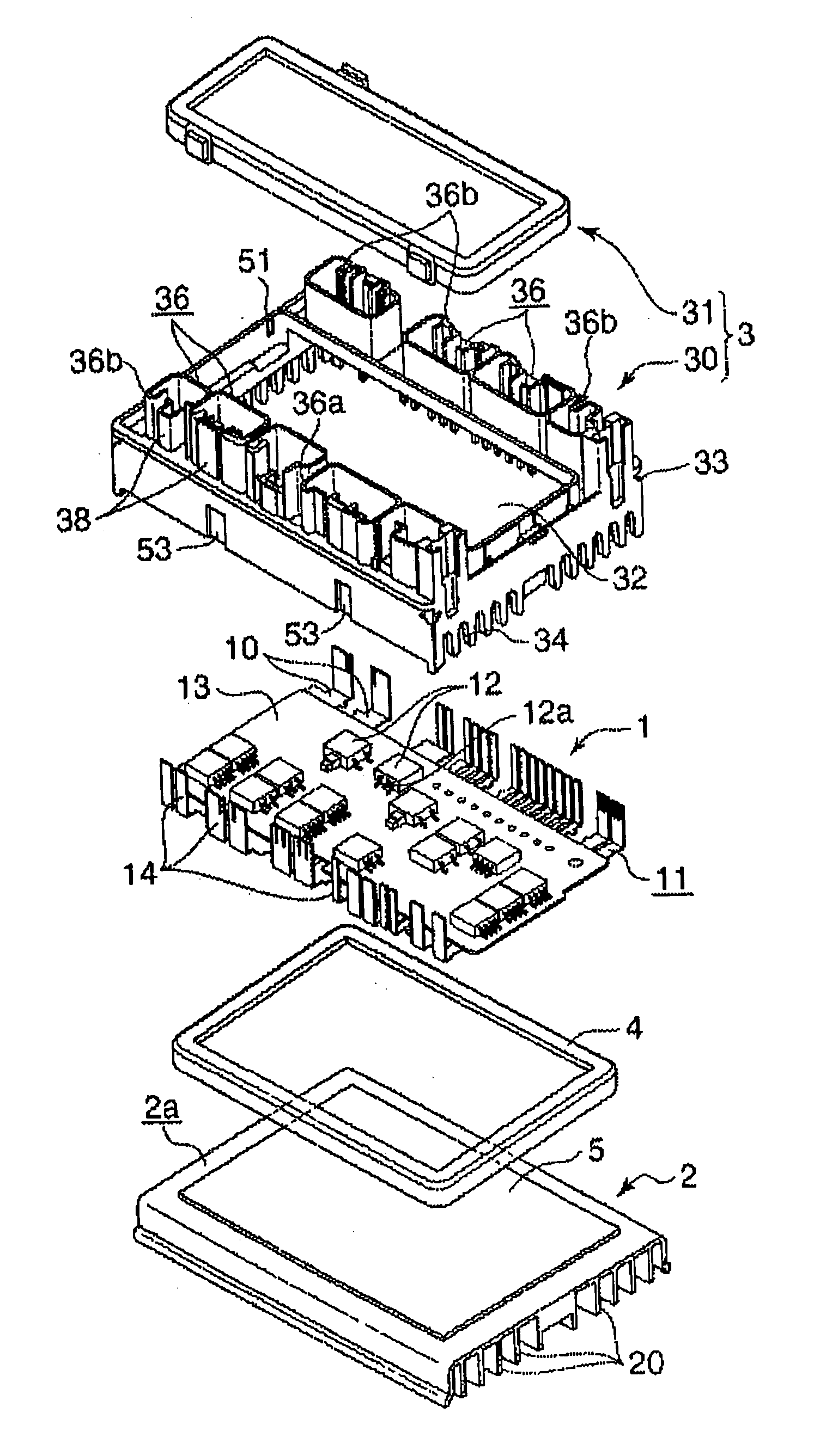
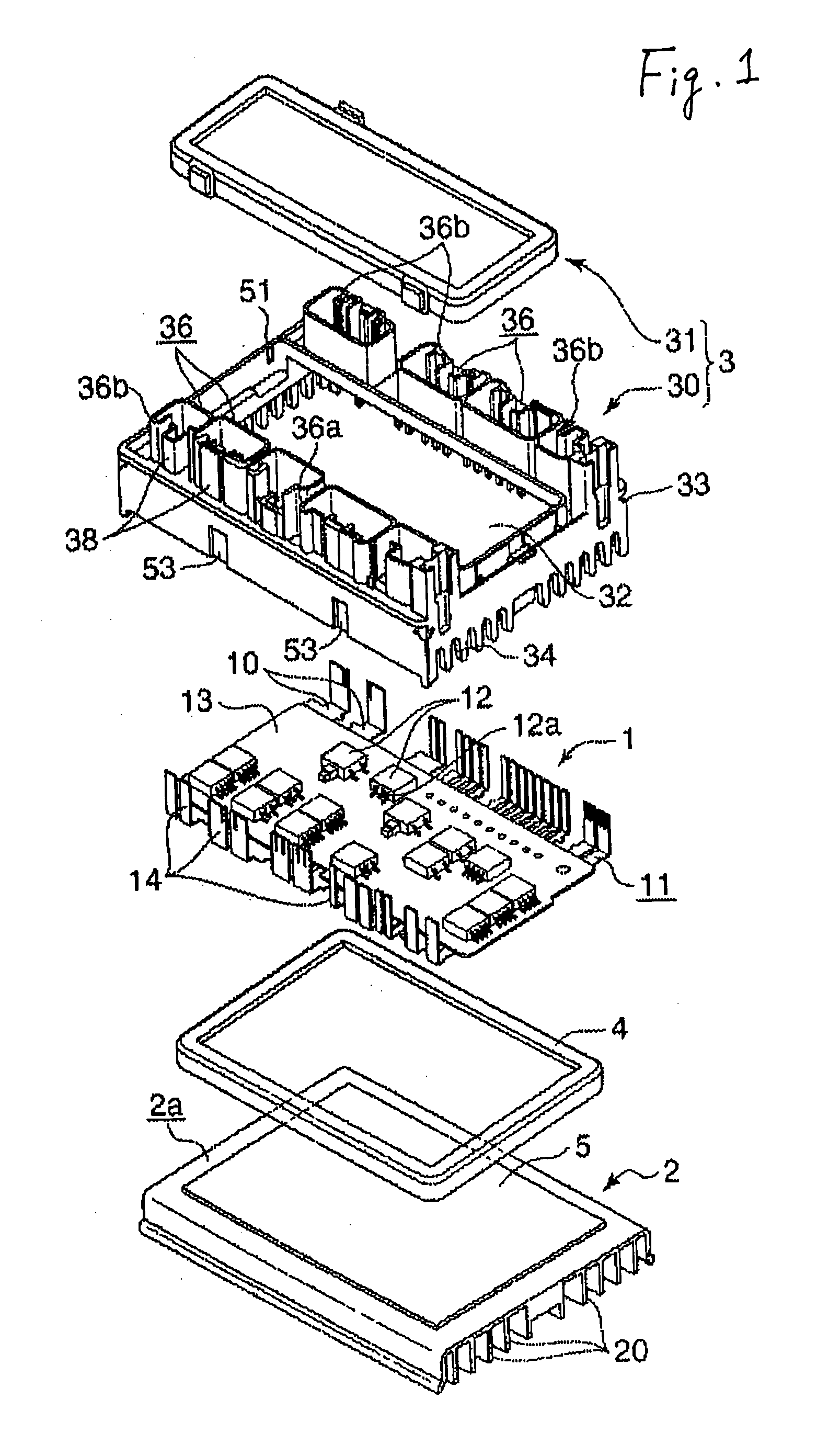
[0031] Referring now to the drawings, embodiments of a power module and a method for producing the power module in accordance with the present invention will be described below. A power module that distributes an electrical power supplied from a common power source on a vehicle or the like to a plurality of electrical loads is described here. However, the present invention is not limited to this power module but can be generally applied to a power module having a heat radiation member and required for waterproof.

[0032] FIG. 1 is an exploded perspective view of an embodiment of a power module in accordance with the present invention. The power module comprises a power circuit section 1 including a plurality of bus...


PUM


Abstract

A power circuit section including a plurality of bus bars is disposed through an insulation layer on a circuit arrangement surface of a heat radiation member. An end of each of the bus bars is folded up from the circuit arrangement surface to form an external connection terminal. An enclosure wall member that surrounds the power circuit section including the external connection terminal is disposed on the heat radiation member. A connector housing contains an external connection connector that comprises a bottom portion provided with terminal, a through-hole into which the external connection terminal is inserted, and a hood that surrounds the external connection terminal. The external connection connector can be coupled to another connector together with the external connection terminal. A waterproof layer is formed within the enclosure wall member so that at least a part of the power circuit section is sealed and the terminal through-hole is sealed.

Description

CLAIM FOR PRIORITY[0001] The present invention claims priority to Japanese Patent Application JP-A-2003-036469 filed Feb. 14, 2003.[0002] 1. Field of Invention[0003] This invention relates to a power module in which a power circuit section including a bus bar and a semiconductor device is disposed through an insulation layer on a heat radiation member. This invention also relates to a method for producing the power module, and more particularly relates to a power module that can be used as, for example, a power distributor for a vehicle for distributing an electrical power to a plurality of electronic units from a common power source on a vehicle, and to a method for producing the power module.[0004] 2. Description of Related Art[0005] Heretofore, as means for distributing a power to each electronic unit from a common power source on a vehicle, a junction box has been known which constitutes a power circuit section in which a plurality of bus bar boards are laminated, and a fuse and...

Claims


Application Information

Patent Timeline
IPC IPC(8): H05K5/02B60R16/02B60R16/023H01R13/52H02G3/16H05K3/20H05K3/28H05K5/06H05K7/02H05K7/20
CPCB60R16/0238H05K3/202H05K3/284Y10T29/4935H05K2201/0397H05K2203/1147H05K7/026
Inventor YAMAGUCHI, JUN
Owner SUMITOMO WIRING SYST LTD
Why Eureka
Try Eureka