
Golf clubhead for putting or striking a golf ball

a golf club and golf ball technology, applied in the field of golf club heads, can solve the problems of loss of a stroke, misdirection of the ball and an impact force other than anticipated, and achieve the effect of only partially effective solutions

Inactive Publication Date: 2004-09-02
ASHTON DAVID PERRY
View PDF6 Cites 8 Cited by
  • Summary
  • Abstract
  • Description
  • Claims
  • Application Information

AI Technical Summary

Problems solved by technology

The force of the ball-club contact towards the toe or the heel causes the clubhead to open or close, sending the ball away from the intended target line, resulting in misdirection of the ball and an other than anticipated impact force.
Off-center impact is especially important for putters, as even a slight deflection can cause a loss of a stroke.
Further invention by U.S. Pat. No. 5,766,093 Rohrer, uses many solid layers of different materials situated side-by-side for the club head construction to improve off-center impacts; but this solution is only partially effective in addition to being costly to manufacture.
The off-center contact remains one of the worst problems in a golf swing, especially for the higher-handicapped golfer.
It is not an easy task for most golfers to align the leading edge (perpendicular axis) of a clubhead at exactly 90 degrees to an imaginary target line.
These dubs provide a long horizontal axis to assist in parallel alignment,; however, due to the wide body shape, an imperfect stroke will tend to catch the bottom of the clubhead on the ground prior to contact with the ball.
Other problems with the above teachings are that the face of the club (perpendicular member) is still a dominant visual feature which contradicts the provided horizontal axis.
With this weight behind the sweetspot, the golfer will experience a heavy impact when the ball is stroked on the sweetspot; but will lose distance and accuracy when the ball is struck away from the center, on the perimeter of the sweetspot.
In addition, the markings on the club in some cases do not represent the true center of the clubhead.
Conventional clubheads do not provide an intuitive alignment feature to assist these golfers in making a precise alignment using the overall clubhead shape.
In addition to the above alignment techniques, the sole (bottom) of the clubs have been traditionally constructed relatively flat or with a slight curve, therefore, not of significant help to the golfer with alignment.
It is well documented that the golfers of all abilities continue to have difficulty with their club alignments.
Conventional dubheads do not provide sufficient assistance to the golfer in taking the club back slower on the backswing, and lack adequate aerodynamic qualities to prevent the club from going off-track while the club is being swung above ground.
One of the most common problems in a golf stroke, especially in putting, is pulling the clubhead across the ball too quickly to the inside of the target line during impact.
The hosel, which is the transition between the shaft and the clubhead, is typically a narrow stem and is not of much assistance in keeping the stroke parallel to the target and keeping the heavy clubhead on track at the moment of contact with the ball, especially on off-center hits.
Since any ball which is struck in the normal mis-hit area (up to 15 mm for a putter), will still have a cavity behind the strike area, the loss of distance problem has not been solved in any of the prior art having a heel-toe-weighting model and or comprising a rear cavity.
Gunderson does not appreciate the cavity in the rear of the putter for any reason other than distributing weight to heel and toe.
This feature as in all prior art is not concerned and does not provide answer to any aerodynamic properties for a golf club.

Method used


Image

  • Golf clubhead for putting or striking a golf ball
  • Golf clubhead for putting or striking a golf ball
  • Golf clubhead for putting or striking a golf ball

Examples


Embodiment Construction

[0059] The specifications herein describe a putter clubhead. Description of iron and metalwood clubheads will be described in the alternative embodiments section.

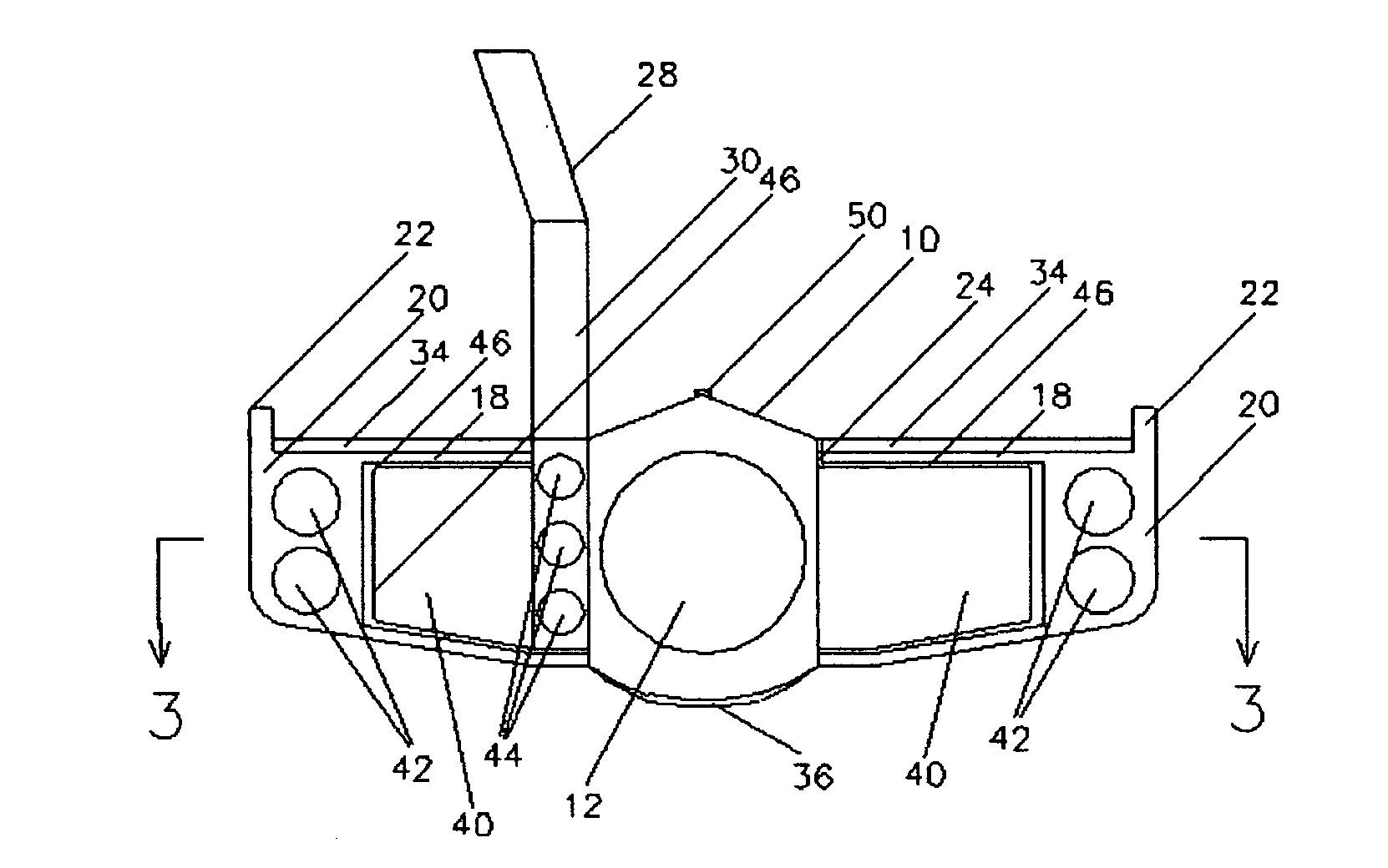
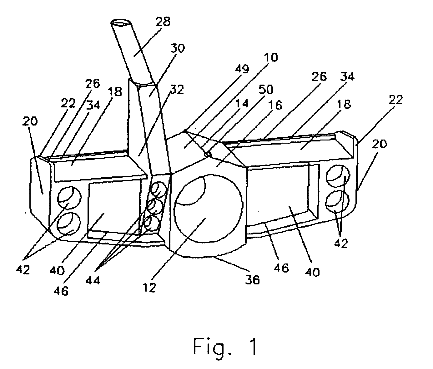
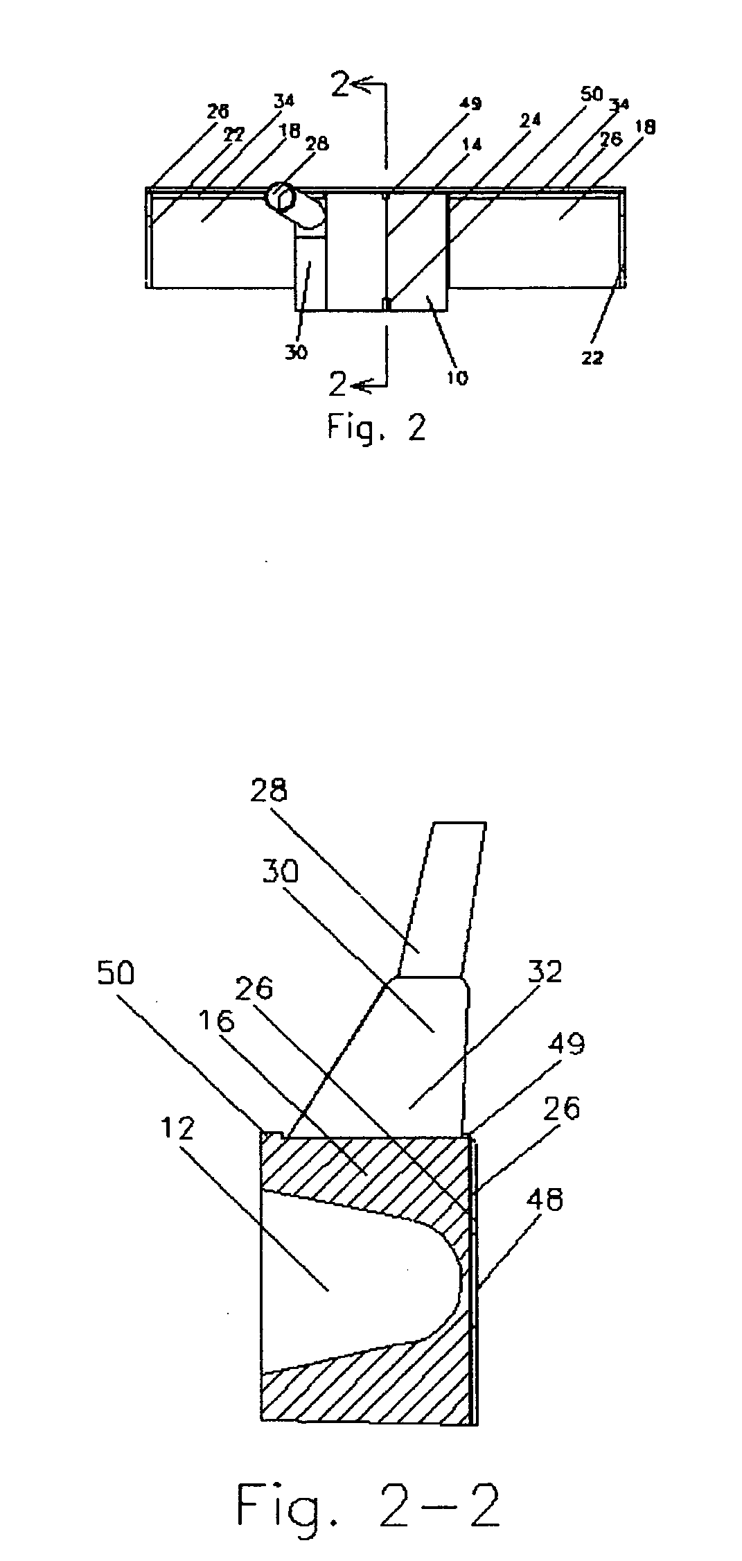
[0060] FIG. 1 shows the rear perspective view from the heel-side of the preferred embodiment of the present invention. My putter clubhead consists of a hollowed tubular shape similar to an abbreviated six-sided gun barrel, named a strike-barrel 10. Clubhead sole 36 is the rounded and somewhat flattened bottom side of strike-barrel 10. Strike barrel 10 is opened from the rear to near the very front of clubhead to create strike-barrel pocket 12. Arms 18 sandwich strike-barrel, which more or less constitutes the center portion of the clubhead. Arm pockets are the openings of each arm from the rear. Hosel 30 is somewhat triangular in shape and connects the shaft 28 to clubhead. The lower portion of hosel 30 contains pockets 44 which are open-ended from the rear. Without hosel 30, the clubhead is generally symmetrical from heel ...


PUM


Abstract

An improved golf clubhead having a hollowed strike-barrel (10) centrally located and positioned parallel on the golfer's intended target line for more precise alignment and efficient on-target stroke. The mass of strike-barrel walls (16) in a graduating manner providing additional force behind the usual-mis-hit-area, therefore compensating for the misdirection and the loss of velocity on off-center strikes. The strike-barrel pocket (12), and any additional pockets in the rear of arms (40), hosel (44), and the heel and toe (42), providing a significant air drag when the clubhead is swung back from the ball, thereby slowing the golfer's backswing. The strike-barrel (10) having gun-barrel type bead-mark sights (49) and (28) on its parallel axis along the target line for improved alignment and stroke. An elongated hosel-base (32) provides assistance to the golfer in keeping the clubhead on track longer.

Description

[0001] This is a continuation of application Serial No. 09 / 966,211.[0002] Filed Sep. 27, 2001.[0003] 1. Field of Invention[0004] This invention relates to golf club heads; specially to an improved clubhead for putters.[0005] 2. Description of Prior Art[0006] Golfers, for centuries, have been struggling for greater distance, accuracy, and consistency on their golf shots. Therefore, inventors have created hundreds (perhaps thousands) of different types of golf clubs to improve these functions by providing:[0007] 1. More effective results from imperfect shots, to achieve more consistency;[0008] 2. Better alignment features, to improve accuracy;[0009] 3. Greater efficiency for the club ball strike, to increase distance.[0010] I Off-center club ball impact constitutes a large percentage of imperfect golf shots. A ball that is struck away from the sweetspot, deflects the club at impact. The force of the ball-club contact towards the toe or the heel causes the clubhead to open or close, se...

Claims


Application Information

Patent Timeline
Patent Type & Authority Applications(United States)
IPC IPC(8): A63B53/04
CPCA63B53/0487A63B2053/0433A63B2053/0441A63B2053/0416A63B60/00A63B53/0416A63B53/0441A63B53/0433
Inventor ASHTON, DAVID PERRY
Owner ASHTON DAVID PERRY
Learn More