Fuel cell structures and assemblies

a technology of fuel cell and structure, applied in the direction of cell components, electrochemical generators, cell component details, etc., can solve the problems of increasing the size of the fuel cell system, the bulky size of the thermal energy management device or the structure used in the conventional fuel cell cogeneration system,

Inactive Publication Date:
View PDF10 Cites 44 Cited by
  • Summary
  • Abstract
  • Description
  • Claims
  • Application Information

AI Technical Summary

Problems solved by technology

The thermal energy managing devices or structures used in conventional fuel cell cogeneration systems are usually very bulky in size, which include various heat exchanging panels, pipes, fluid pumps, and tubings, for which significant space is required, in additional to that of the fuel cell itself.
Such humidifying devices or structures further increase the size of the fuel cell system.

Method used


Image

  • Fuel cell structures and assemblies
  • Fuel cell structures and assemblies
  • Fuel cell structures and assemblies

Examples


Embodiment Construction

[0040] The contents of U.S. Pat. Nos. 5,916,514, 5,928,808, 5,989,300, 6,338,913, 6,399,232, 6,403,248, 6,403,517, 6,444,339, 6,495,281, and U.S. Provisional Patent Application No. 60 / 452,635, filed Mar. 7, 2003 are incorporated herein by reference in their entireties for all purposes.

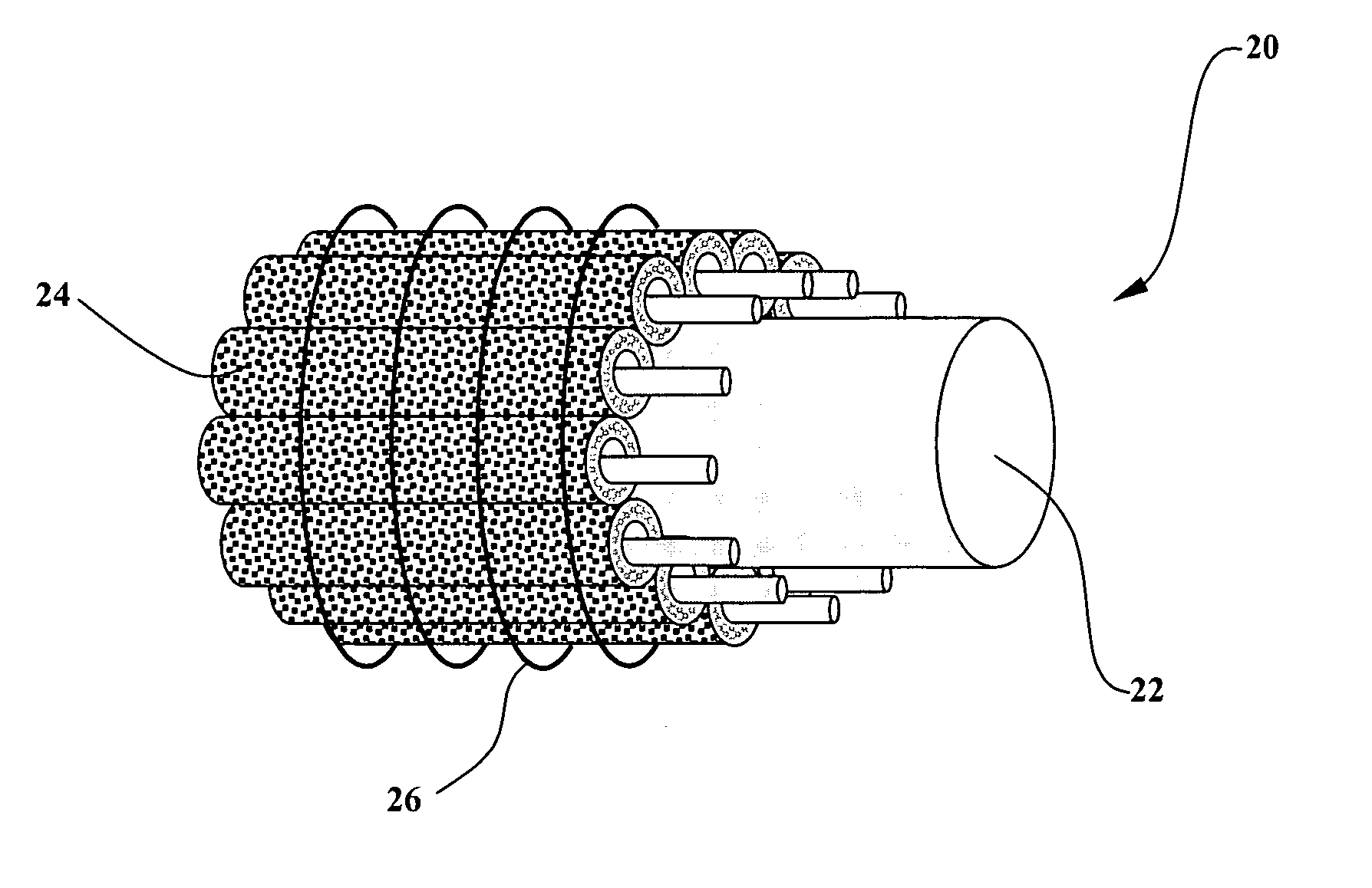
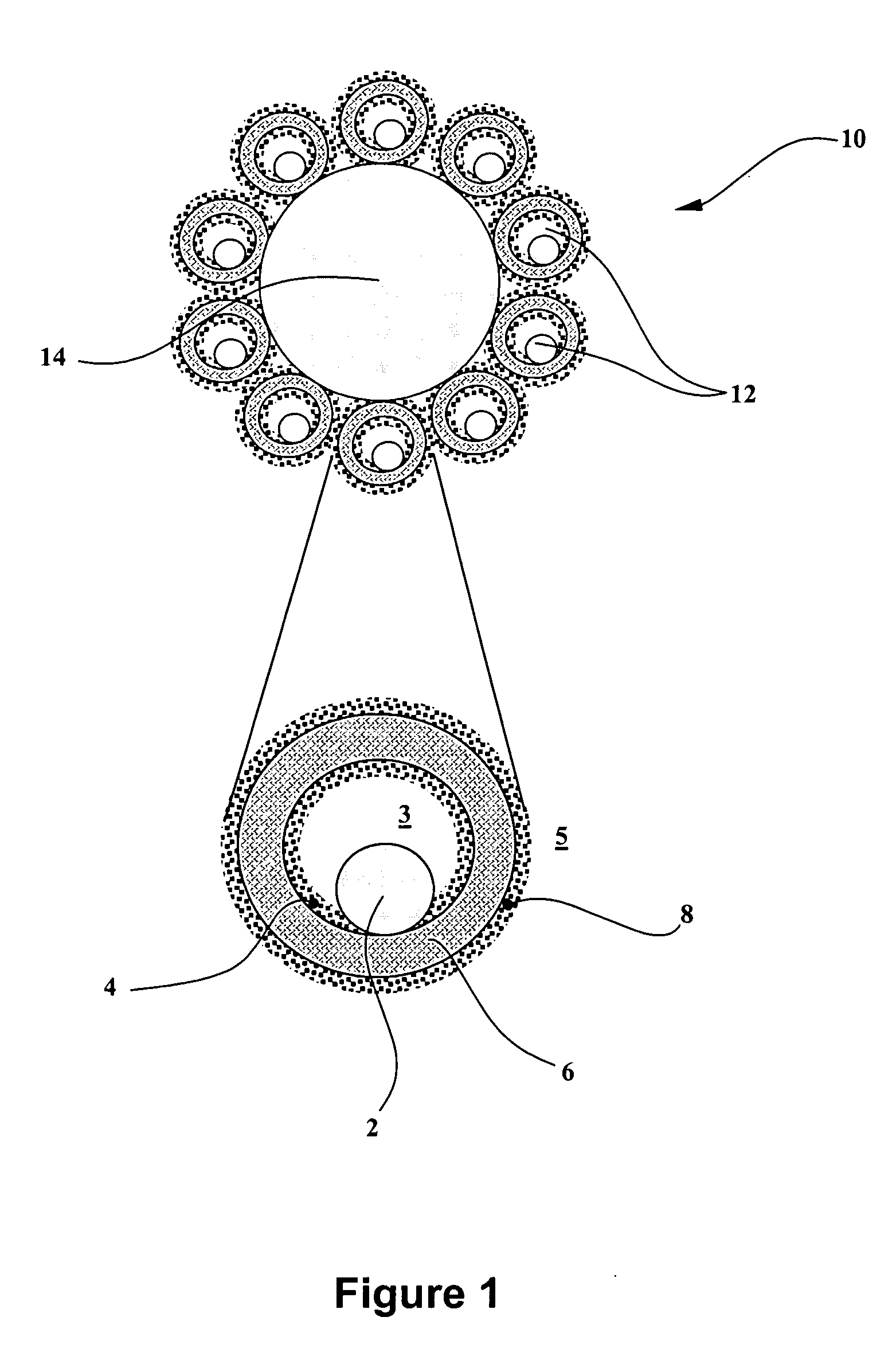
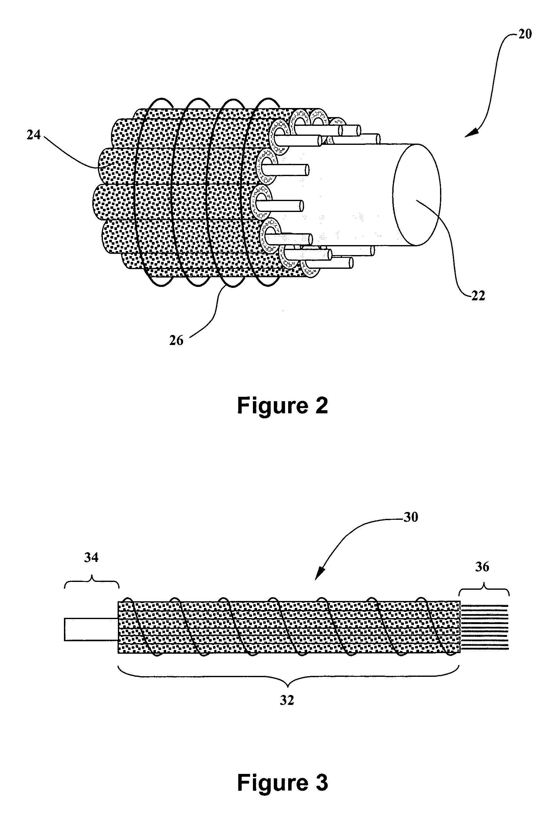
[0041] The terms "microfibrous," "fibrous," and "fiber" are used interchangeably herein for defining an elongated structure having a cross-sectional outer diameter in a range of from about 10 microns to about 10 millimeters, preferably 100 microns to about 10 millimeters, more preferably from about 10 microns to about 5 millimeters, and most preferably from about 10 microns to about 1 millimeter.

[0042] The terms "tubular" and "tube" are used herein for defining an elongated structure having a cross-sectional outer diameter of at least one millimeter, preferably at least 1 centimeter, and more preferably at least 5 centimeters.

[0043] The terms "porous" and "microporous" are used interchangeably herein f...


PUM

PropertyMeasurementUnit
outer diameteraaaaaaaaaa
diametersaaaaaaaaaa
outer diameteraaaaaaaaaa

Abstract

The present invention relates to microfibrous fuel cell sub-bundle structures, fuel cell bundles and fuel cell assemblies formed by such fuel cell sub-bundles and bundles. Specifically, a fuel cell sub-bundle is provided, which comprises multiple microfibrous fuel cells. Each microfibrous fuel cell comprises: (a) a hollow microfibrous membrane separator comprising an electrolyte medium, (b) an inner electrocatalyst layer in contact with an inner surface of such membrane separator, (c) an outer electrocatalyst layer in contact with an outer surface of such membrane separator, and (d) an individual current collector in electrical contact with the inner surface of such membrane separator. Each of such multiple microfibrous fuel cells is in electrical contact with a common current collector at the outer surface of its membrane separator.

Description

[0001] This claims priority to U.S. Provisional Patent Application No. 60 / 452,635, filed Mar. 7, 2003 in the names of Ray R. Eshraghi and Michael W. Riley for "MICROFIBROUS FULE CELL ASSEMBLIES WITH INTEGRAL THERMAL AND / OR HUMIDITY MANAGEMENT SYSTEMS."[0003] 1. Field of the Invention[0004] This invention in general relates to fuel cell structures and assemblies, and more specifically to fuel cell structures and assemblies that comprise multiple microfibrous fuel cell elements arranged and constructed for efficient thermal and / or humidity management.[0005] 2. Description of the Related Art[0006] In recent years, fuel cell or fuel cell assembly has become more and more available as a power source for use in handheld or mobile electrical devices, electrically powered vehicles, as well as in distributed power generation applications.[0007] Fuel cells offer especially attractive prospects as energy conversion devices, by exhibiting high energy efficiency and low levels of gaseous / solid e...

Claims


Application Information

Patent Timeline
Patent Type & Authority Applications(United States)
IPC IPC(8): H01M8/02H01M8/04H01M8/10H01M8/24H01M50/77
CPCH01M8/004Y02E60/521H01M8/0228H01M8/0247H01M8/0252H01M8/04014H01M8/1002H01M8/1023H01M8/1032H01M8/1039H01M8/241H01M8/247H01M8/2485H01M8/249H01M8/0204H01M8/1007Y02E60/50H01M8/0267
Inventor ESHRAGHI, RAY R.RILEY, MICHAEL W.
Why Eureka
Try Eureka