
Isolated motor pan for watercraft

a technology of isolated motors and watercraft, which is applied in the direction of marine propulsion, special-purpose vessels, vessel construction, etc., can solve the problems of reducing the enjoyment of watercraft passengers, high vibration levels and high vibration on the deck of watercra

Inactive Publication Date: 2004-09-09
PONTOON BOAT
View PDF5 Cites 2 Cited by
  • Summary
  • Abstract
  • Description
  • Claims
  • Application Information

AI Technical Summary

Benefits of technology

"The present invention relates to a watercraft with a frame and a motor. The invention aims to reduce the transfer of vibration from the motor to the deck of the watercraft. The invention includes a dampening assembly that isolates the motor from the frame, limiting the travel path of the motor vibrations. This isolation reduces the vibration energy that is transferred into the deck, improving the comfort and enjoyment of the watercraft. The dampening assembly includes a first cross member, a second cross member, and a bushing, which is positioned between the frame and the motor pan to absorb the vibration energy. The invention also includes a shim to position the motor pan at a level below the frame to further reduce vibration transfer. Overall, the invention improves the performance and comfort of watercraft with outboard motors."

Problems solved by technology

Traditionally, the direct mounting of the motor to the frame of the watercraft allows the transfer of vibrations from the motor directly to the deck of the watercraft, thereby creating high levels of vibration in the deck.
High levels of vibration in the deck of a watercraft can be problematic for a variety of reasons.
For example, the high vibration levels can reduce the enjoyment of the passengers in the watercraft.
Furthermore, high levels of vibration may also loosen fasteners in the watercraft, such as screws or bolts, thereby requiring an operator to perform frequent maintenance in order to ensure that the fasteners remain secure.

Method used


Image

  • Isolated motor pan for watercraft
  • Isolated motor pan for watercraft
  • Isolated motor pan for watercraft

Examples


Embodiment Construction

[0020] The embodiments of the invention described herein are not intended to be exhaustive, nor to limit the invention to the precise forms disclosed. Rather, the embodiments selected for description have been chosen to enable one skilled in the art to practice the invention.

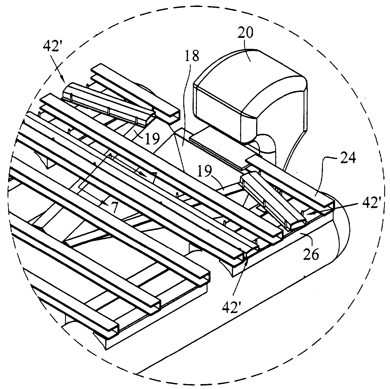
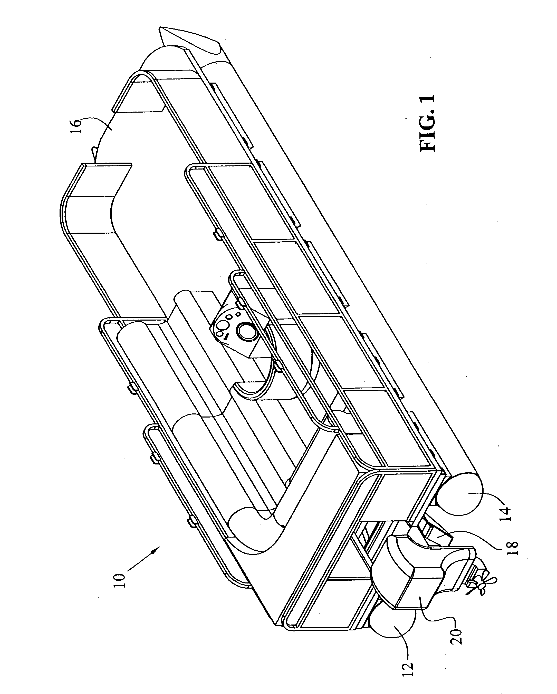
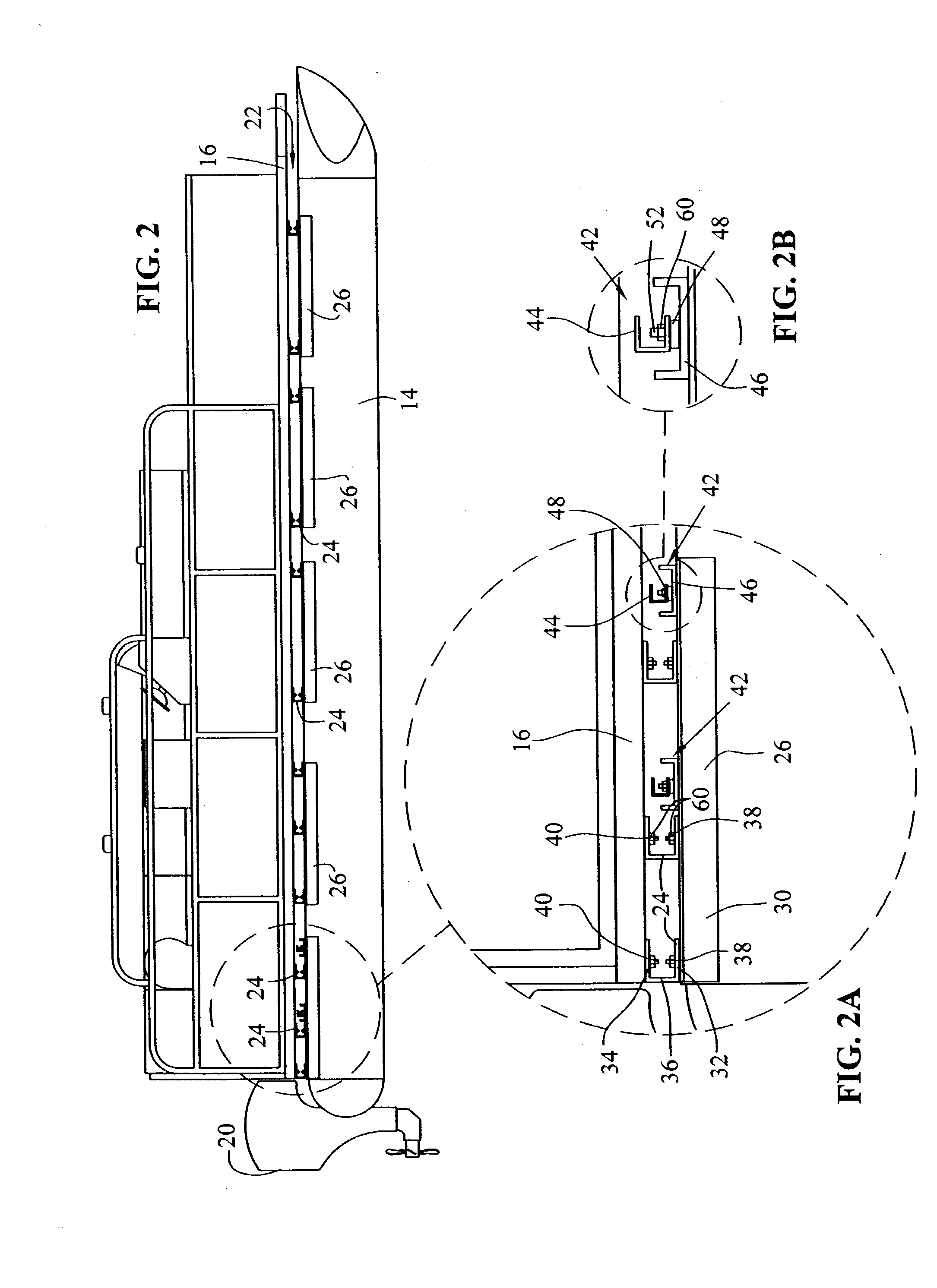
[0021] Referring first to FIG. 1, numeral 10 generally indicates a watercraft. Although the type of watercraft that may be used in conjunction with this invention may vary, the watercraft 10 illustrated in FIG. 1 is generally referred to as a pontoon boat. In the embodiment depicted, watercraft 10 includes a first pontoon 12, a second pontoon 14, a deck 16, a motor pan 18 and a motor 20. Although the watercraft 10 includes only two pontoons 12, 14 in the present embodiment, the number of pontoons may be increased as is known in the art without varying from the spirit and scope of this invention. In addition, in other embodiments of the invention, the watercraft 10 may be a different type of watercraft including ...


PUM


Abstract

A dampening assembly used in watercraft to isolate the motor from the deck of the watercraft. In an embodiment of the invention, a frame including cross-members and a plurality of brackets supports the deck. The dampening assembly of the present invention extends from the brackets of the frame to the motor and retains the motor at a position ensuring the motor does not contact the frame. The only path available to the vibrations generated by the motor is represented by the dampening assemblies that direct the vibrations to the brackets and tubes, thereby eliminating the high amplitude, low frequency vibrations that readily transfer throughout the deck and frame structure. In this manner, the vibrations are prevented from traveling directly through the cross-members of the frame and into the deck of the watercraft.

Description

[0001] 1. Field of the Invention[0002] The present invention relates to the reduction of the transfer of vibration in watercraft. Specifically, the present invention relates to the isolation of the motor from the deck of a watercraft.[0003] 2. Description of the Prior Art[0004] Generally, in the field of watercraft, the propulsion unit, or motor as it is commonly referred to, is mounted directly to the frame of the watercraft. Standard motor units, notably those of the outboard variety, are commonly known to vibrate, especially at low speeds. Traditionally, the direct mounting of the motor to the frame of the watercraft allows the transfer of vibrations from the motor directly to the deck of the watercraft, thereby creating high levels of vibration in the deck.[0005] High levels of vibration in the deck of a watercraft can be problematic for a variety of reasons. For example, the high vibration levels can reduce the enjoyment of the passengers in the watercraft. Furthermore, high le...

Claims


Application Information

Patent Timeline
Patent Type & Authority Applications(United States)
IPC IPC(8): B63B1/12B63B3/48B63B3/70B63H1/15B63H20/06B63H21/30
CPCB63B1/121B63B3/48B63H21/305B63H20/06B63B3/70
Inventor FISHBURN, BRADLEY R.WARFEL, JEREMIAH S.
Owner PONTOON BOAT
Learn More