Method for the production of a valve

a production method and valve technology, applied in the field of valve production methods, can solve the problems of large amount of production rejection, difficult to precisely set the desired switching stroke, and relatively complex production of such valves, and achieve the effect of reliable valve production

Inactive Publication Date: 2004-09-16
FESTO AG & CO KG
View PDF6 Cites 24 Cited by
  • Summary
  • Abstract
  • Description
  • Claims
  • Application Information

AI Technical Summary

Benefits of technology

0005] One object of the present invention is to provide a method which irrespectively of manufa

Problems solved by technology

Owing to the presence of manufacturing inaccuracies of the components the production of such valves is relatively complex.
More especially in the case of valves with very small dimensions and more particularly micro-valves, the manufacturing inaccuracies are very prone to have a size near the size of the switching stroke of the valve member so that it is extremely difficult

Method used


Image

  • Method for the production of a valve
  • Method for the production of a valve
  • Method for the production of a valve

Examples


Embodiment Construction

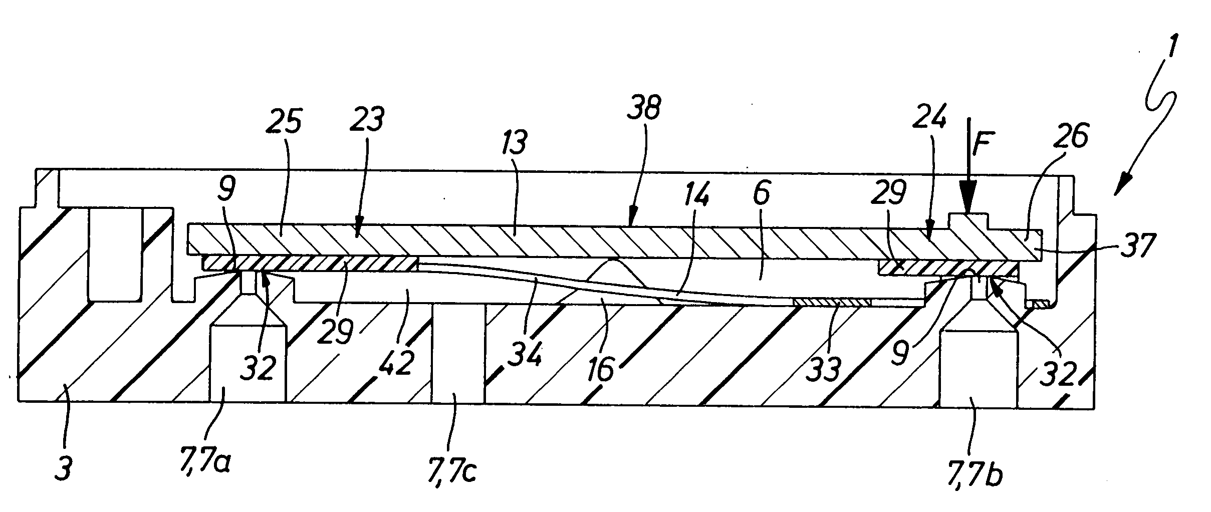
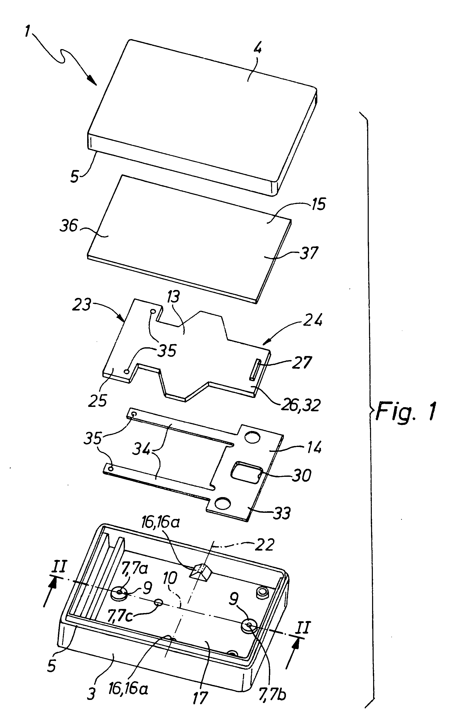
[0027] The valves 1 illustrated in drawing are more particularly suitable for the application of the method of the invention. However, the method may also be applied for valves with a different design.

[0028] Firstly there will be a description of a preferred structure of the valve 1 to be subjected to the method of the invention.

[0029] The valve 1 may have comparatively small dimensions so that it could be termed a micro-valve. More particularly in conjunction with valves with small and minimum dimensions advantageous application of the method is possible. However, it may be applied to valves of any dimensions.

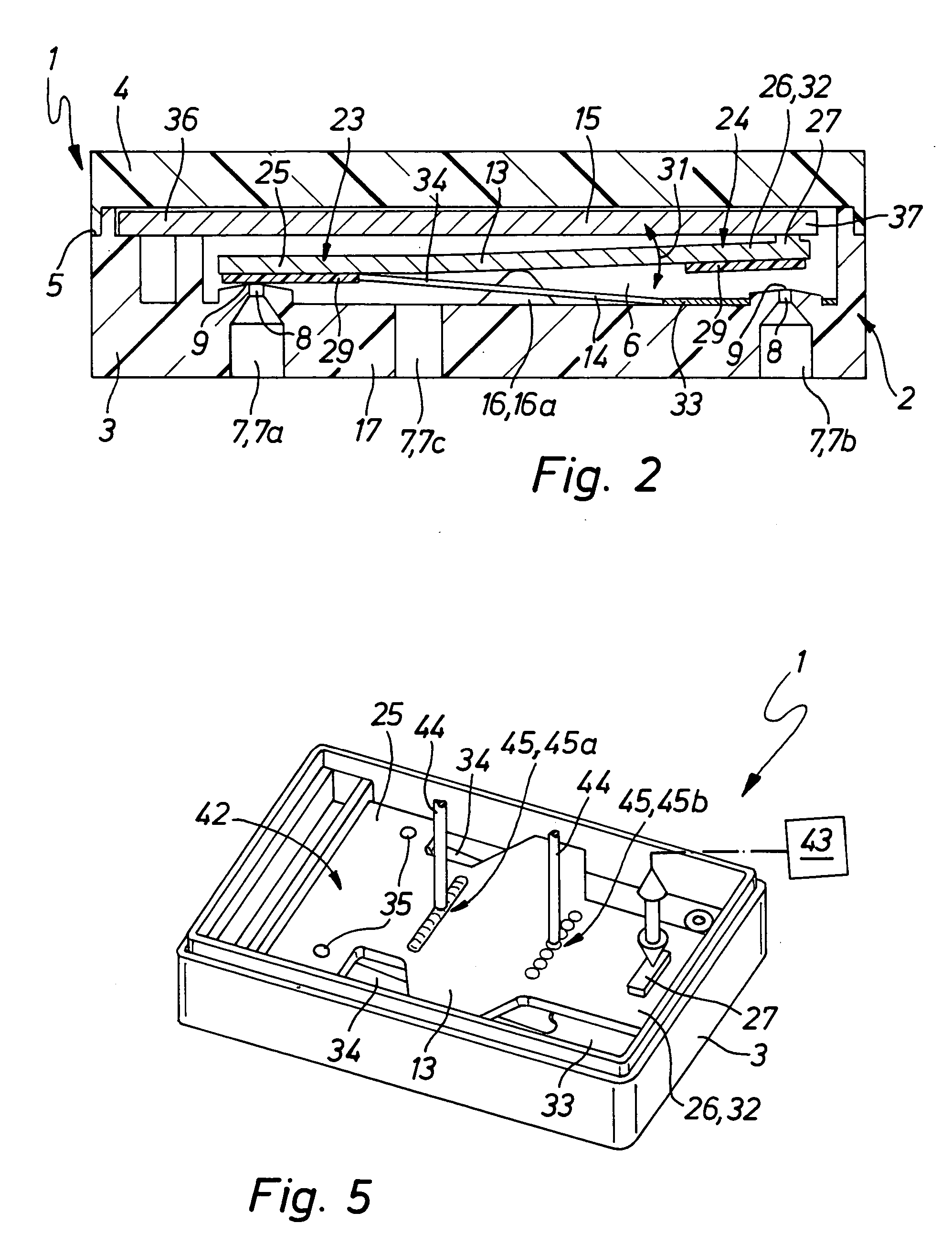
[0030] The valve 1 has a housing 2, which in the working embodiment illustrated is composed of a housing bottom part 3 and a housing cover 4 secured to it in a sealing fashion. These two parts are preferably produced by injection molding, more especially using plastic material. The connection in the joint region 5 is preferably performed by laser welding or by bonding. In the ...


PUM

PropertyMeasurementUnit
Energyaaaaaaaaaa
Deformation enthalpyaaaaaaaaaa

Abstract

A method for the manufacture of a valve having at least one valve opening surrounded by at least one valve seat and an elongated valve member able to be brought into different positions by pivoting. In order to adjust the switching stroke of the valve member the valve member is, for instance using a laser, locally and briefly heated until superficial plastification occurs so that in the direction of the pivoting movement performed in operation it experiences a permanent flexural deformation.

Description

[0001] The invention relates to a method for the production of a valve, which comprises at least one valve opening surrounded by a valve seat and furthermore an elongated valve member able to be positioned by pivoting selectively into a closing position with a closure section resting on the at least one valve seat or into an open position clear of the valve seat.THE PRIOR ART[0002] For the control of fluid flows various different types of electrically operated valve are employed, which possess an elongated valve member, which is able to be switched over in a pivoting movement between different positions. The German patent publication 19,957,953 A1 describes such a valve in the case of which the valve member is constituted by piezoelectric flexural transducer which is held at one end thereof. The European patent publication 1158182 A1 describes a valve, which has a pivotally mounted rocker-like valve member and which by the action of a piezoelectric flexural transducer is able to be ...

Claims


Application Information

Patent Timeline
IPC IPC(8): F16K31/00
CPCY10T29/49423F16K31/006Y10T137/86847Y10T137/86622Y10T137/0502
Inventor WEINMANN, MICHAELMUNZ, GEBHARDMAICHL, MARTINMUNZENMAIER, ANDREAS
Owner FESTO AG & CO KG
Why Eureka
Try Eureka