Light pen, photo detective liquid crystal display device and display device having the light pen
a liquid crystal display device and light pen technology, applied in the field of light pen, can solve the problems of display device scratching and damage, user fatigue, display device having lens,
- Summary
- Abstract
- Description
- Claims
- Application Information
AI Technical Summary
Problems solved by technology
Method used
Image
Examples
embodiment 6
of a Light Pen
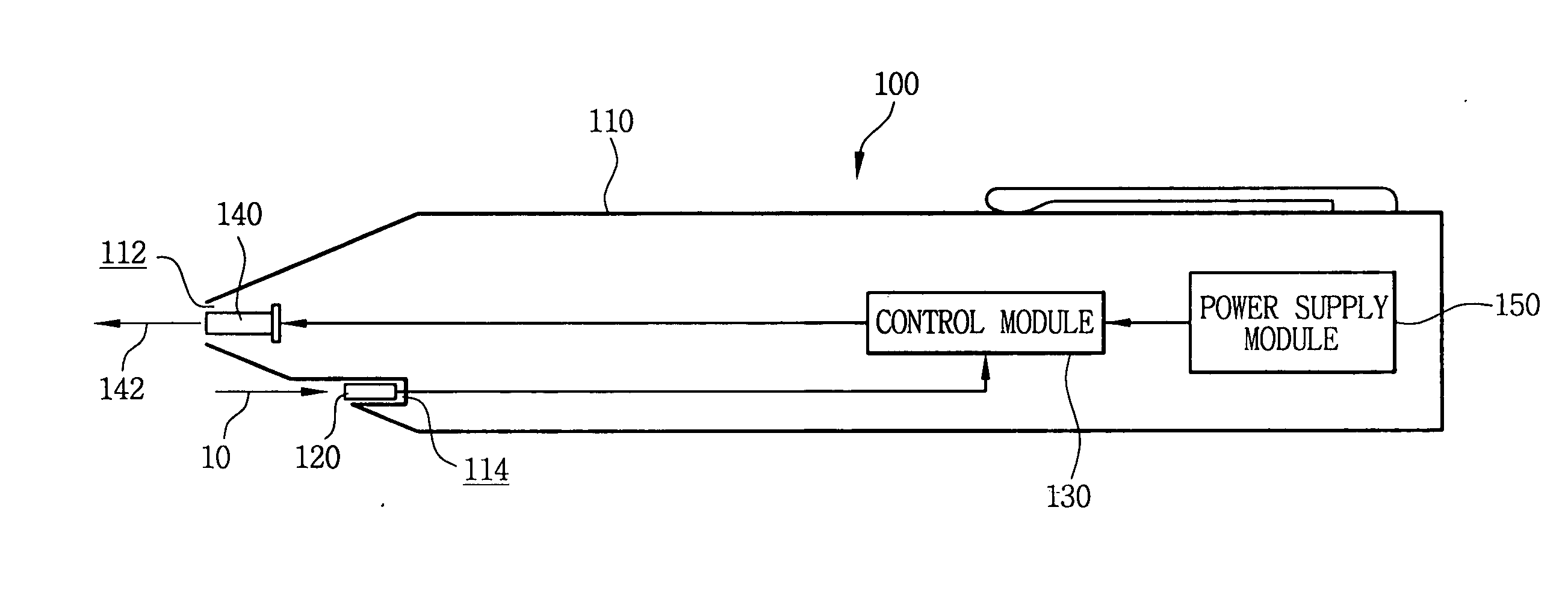
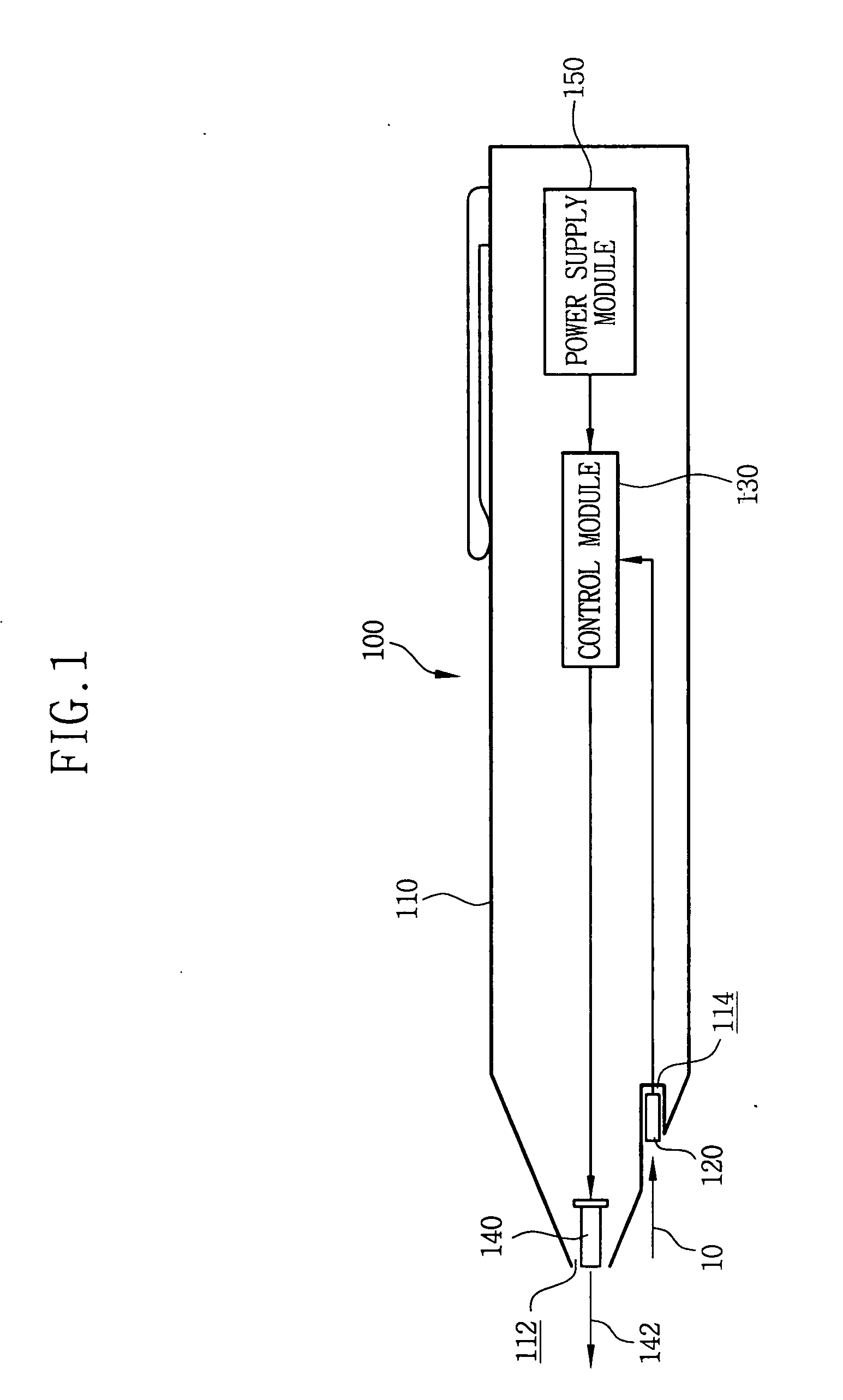
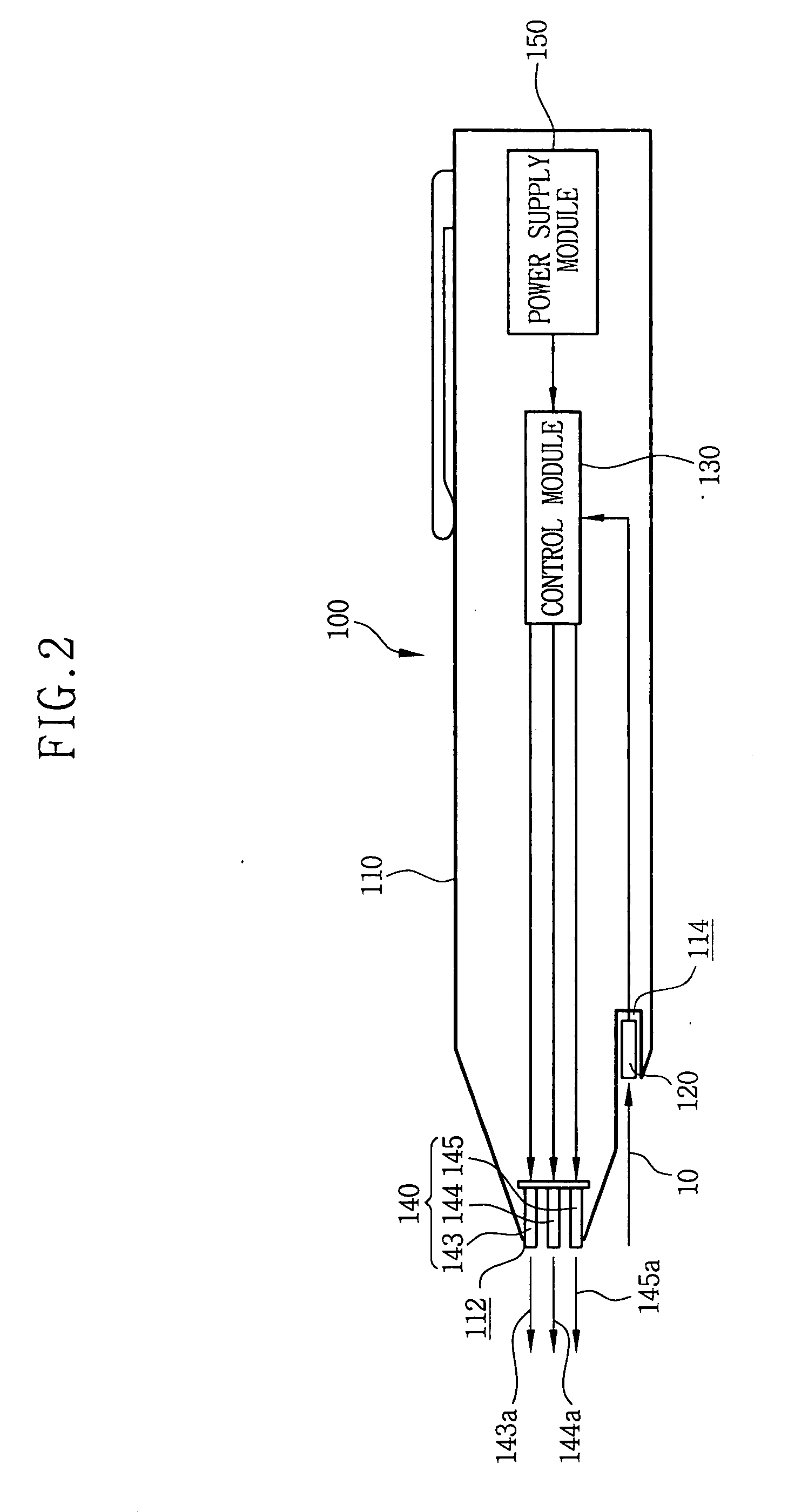
[0093] FIG. 8 is a schematic view showing a light pen according to a sixth exemplary embodiment of the present invention. In embodiment 6, all elements except a driving pulse generating module denote the same elements in embodiment 4, and will not be further described below to avoid a redundancy.
[0094] Referring to FIG. 8, the driving pulse generating module 135 is installed in the control module 130. The driving pulse generating module 135 includes a circuit that converts a DC power signal into a pulse signal. The driving pulse generating module 135 generates a first pulse having a first frequency during a first time period and a second pulse having a second frequency during a second time period. The first and second pulses are outputted to the light generating module 140.
[0095] FIG. 9 is a graph showing first and second driving power pulses generated from a driving pulse generating module of FIG. 8.
[0096] Referring to FIGS. 8 and 9, the driving pulse generating modul...
embodiment 7
of a Light Pen
[0106] FIG. 11 is a graph showing first and second driving power pulses generated from a driving pulse generating module according to a seventh exemplary embodiment of the present invention. In embodiment 7, all elements except the pulses generated from the driving pulse generating module denote the same elements in embodiment 1, and will not be further described below to avoid a redundancy.
[0107] Referring to FIGS. 8 and 11, the driving pulse generating module 135 generates a first pulse 136 having a first frequency and a first intensity S1 during a first time period T1. The first pulse 136 has the first cycle period T.sub.A and a first pulse width D.sub.1.
[0108] The driving pulse generating module 135 outputs a second pulse 138 having the second frequency after the first time period T1. The driving pulse generating module 135 outputs the second pulse 138 for the second time period T2. The second pulse 138 has the second cycle period T.sub.B, a second intensity S2 lar...
embodiment 8
of a Light Pen
[0115] FIG. 13 is a partial cross-sectional perspective view showing a light pen according to an eighth exemplary embodiment of the present invention.
[0116] Referring to FIG. 8, the light pen 100 includes a body 180 and a light guiding unit 190. The body 180 has a shape of a pen and has an opening 183 from which light exit at a first end 185 of the body 180.
[0117] The light guiding unit guides the sensing light generated from an external source into the body 180 toward the first end of the body 180. For example, the light guiding unit 190 includes an optical cable having at least one optical fiber.
[0118] A light entering part 192 is connected to dummy pixels disposed on a non-effective display region of the liquid crystal display panel. The sensing light generated from an external source is incident into the light entering part 192. The light exiting from the dummy pixels is incident into the light guiding unit 190 and exits from a light exiting part 194. Optionally, t...
PUM
 Abstract
Description
Claims
Application Information
 - R&D
- Intellectual Property
- Life Sciences
- Materials
- Tech Scout
- Unparalleled Data Quality
- Higher Quality Content
- 60% Fewer Hallucinations
Browse by: Latest US Patents, China's latest patents, Technical Efficacy Thesaurus, Application Domain, Technology Topic, Popular Technical Reports.
© 2025 PatSnap. All rights reserved.Legal|Privacy policy|Modern Slavery Act Transparency Statement|Sitemap|About US| Contact US: help@patsnap.com


