
Moment decision for packet data transmission based on analysis of power control commands

a power control and packet data technology, applied in data switching networks, instruments, frequency-division multiplexes, etc., can solve the problems of increasing uplink signalling, increasing interference in a radio cell, and reducing the actual transmission capacity, so as to reduce interference caused to other users, improve the quality of the radio channel, and reduce the transmission power

Inactive Publication Date: 2004-09-30
NOKIA CORP
View PDF6 Cites 12 Cited by
  • Summary
  • Abstract
  • Description
  • Claims
  • Application Information

AI Technical Summary

Benefits of technology

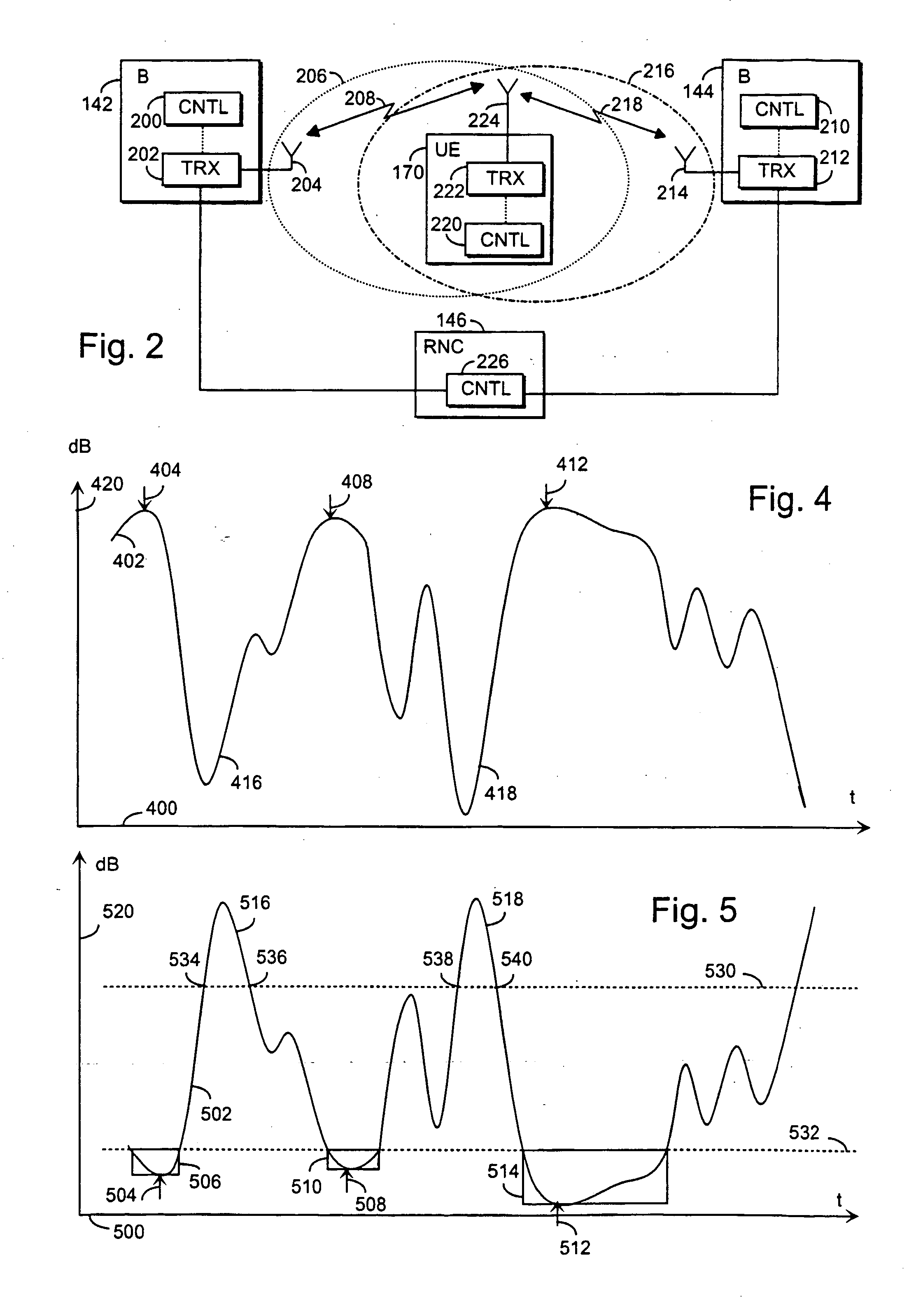
[0012] The invention have advantages, for instance, that the packet transmission being timed for periods when the quality of the radio channel is good, it is possible to transmit the packets with lower transmission power, and consequently interference caused to other users is diminished. It is also more likely that the packet transmission is successful, and so, because there is less need for retransmission, the transmission capacity can be employed more effectively. In addition, there is no need to make the user equipment software more complex, because the implementation of the invention does not necessarily require any changes in the existing user equipments of GSM and WCDMA systems, for instance.

Problems solved by technology

The packet transmission has a problem that large amounts of data are transmitted within a short period of time.
If the transmission fails, for instance due to a fading radio channel, it may be necessary to retransmit the corrupted packets, which decreases the actual transmission capacity and increases interference in a radio cell.
This solution, in turn, has a problem that uplink signalling increases and consequently network loading and interference caused to other users.
In addition, the user equipment software becomes more complex and a need for memory space grows.

Method used


Image

  • Moment decision for packet data transmission based on analysis of power control commands
  • Moment decision for packet data transmission based on analysis of power control commands
  • Moment decision for packet data transmission based on analysis of power control commands

Examples


Embodiment Construction

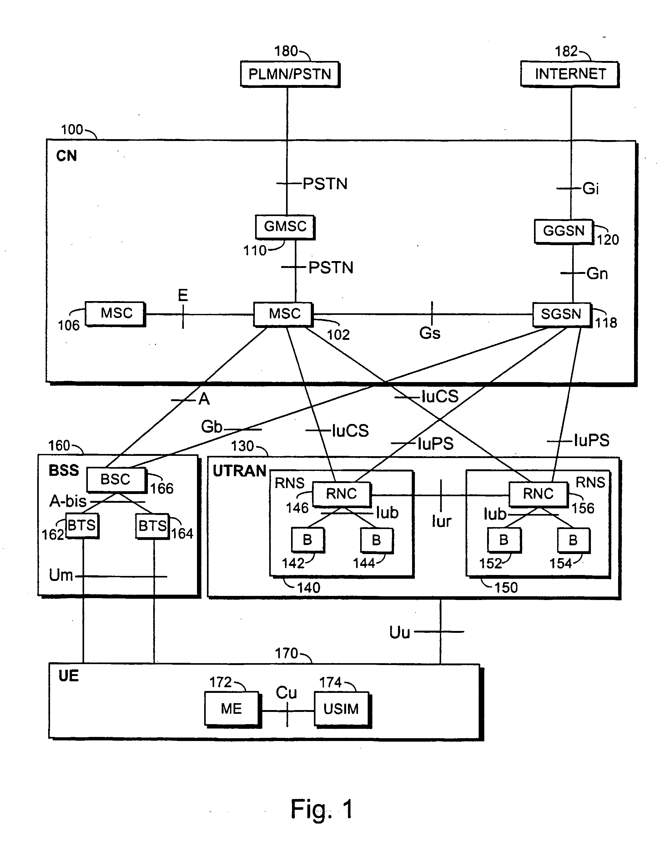
[0021] Because the second generation radio systems and the third generation radio systems, as well as various hybrids thereof, i.e. the so-called generation 2.5 radio systems, are already in worldwide use and under continuous development, the embodiments are described in a simplified radio system of FIG. 1, which comprises network elements of different generations side by side. In the description, the second generation radio system is represented by the GSM (Global System for Mobile Communications), the third generation radio system is represented by a radio system based on the GSM and employing EDGE (Enhanced Data Rates for Global Evolution) technology for enhancing data transmission rates, which radio system can also be used for implementing packet transmission in the GPRS (General Packet Radio System). The third generation radio system is also represented by a radio system that is known under names IMT-2000 (International Mobile Telecommunications 2000) and UMTS (Universal Mobile...


PUM


Abstract

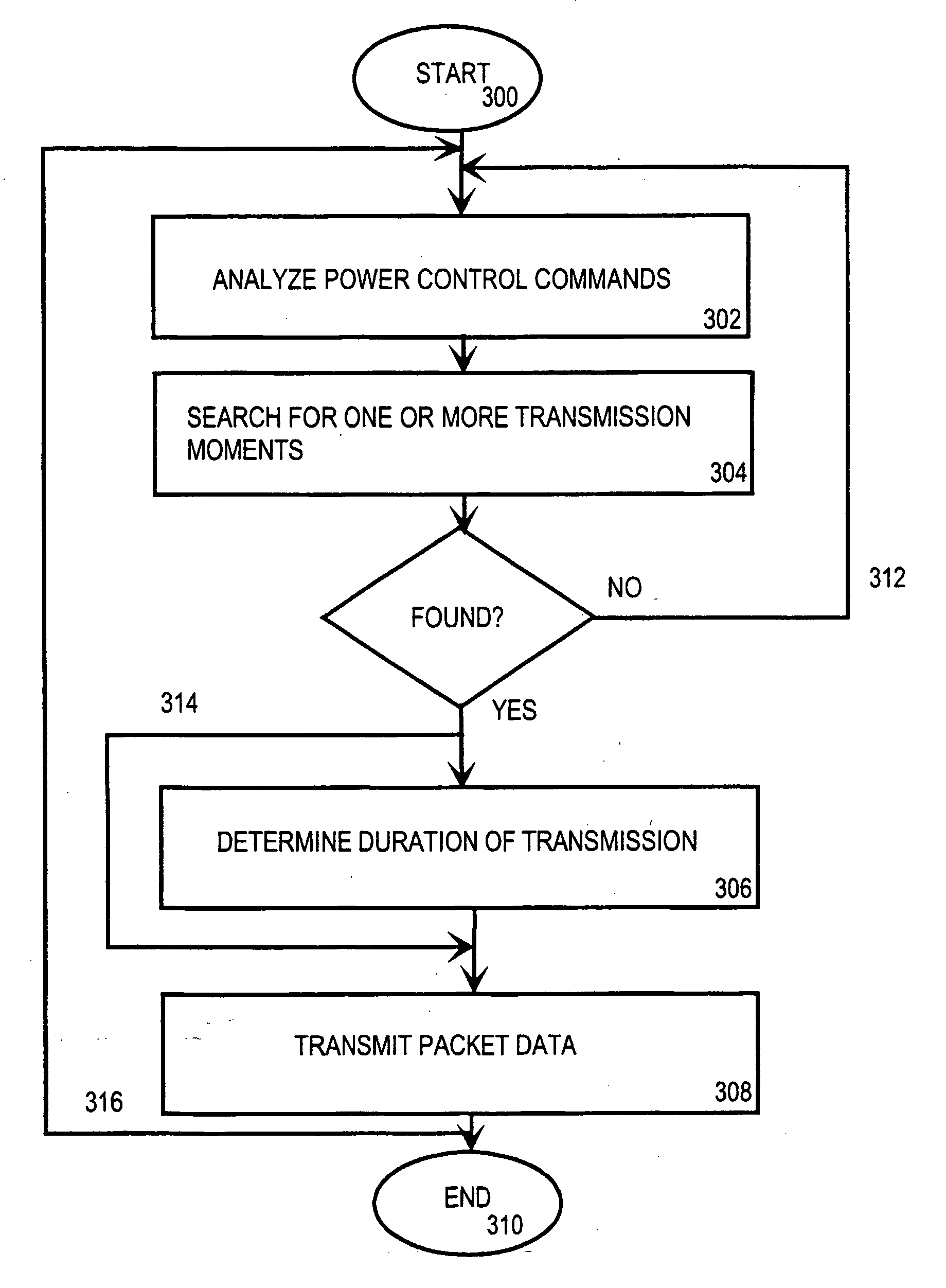
The invention relates to a method for transmitting packet data in a radio system, the radio system comprising at least one base station and at least one subscriber terminal and a downlink power control arrangement, in which power control arrangement the quality of a signal transmitted by the base station is evaluated and, on the basis of this evaluation, power control commands are transmitted to the base station. The method comprises analysing (302) the power control commands received by the base station, searching (304) for one or more transmission moments, on the basis of the analysis, that satisfy the set conditions for packet-switched data transmission, and if at least one transmission moment is found that satisfies the set conditions, transmitting (306) packet data to at least one subscriber terminal at least at one transmission moment that satisfies the set conditions.

Description

FIELD[0001] The invention relates to a method, an arrangement and a base station for transmitting packet data in a radio system, the radio system comprising at least one base station and at least one subscriber terminal and a downlink power control arrangement, in which power control arrangement the quality of a signal transmitted by the base station is evaluated and, on the basis of this evaluation, power control commands are transmitted to the base station.[0002] Requirements set for the data transmission capacity of radio systems are getting higher and higher. A need has arisen to provide a solution for the data transmission capacity required by fast and demanding data transmission, such as the Internet connections. One solution is packet data transmission. In the packet transmission, data to be transmitted is formed into packets that will be transmitted, when there is transmission capacity in the radio network; thus, transmission is discontinuous in nature. Packet transmission i...

Claims


Application Information

Patent Timeline
Patent Type & Authority Applications(United States)
IPC IPC(8): H04B7/005
CPCH04W52/225H04W52/221
Inventor HAMALAINEN, JYRIYLITALO, JUHA
Owner NOKIA CORP
Learn More