Laser liner creation apparatus and method

a technology of laser liner and creation apparatus, which is applied in the direction of earth drilling tools, drilling accessories, borehole/well accessories, etc., can solve the problems of preventing water from mixing with oil, presenting an additional financial cost to the well completion operation, and affecting the completion of the well

Inactive Publication Date: 2004-10-07
GAS TECH INST
View PDF10 Cites 89 Cited by
  • Summary
  • Abstract
  • Description
  • Claims
  • Application Information

AI Technical Summary

Problems solved by technology

These liners present an additional financial cost to the well completion operation, in addition to the time required to put them in place.
Another problem associated with traditio...

Method used


Image

  • Laser liner creation apparatus and method
  • Laser liner creation apparatus and method
  • Laser liner creation apparatus and method

Examples


Embodiment Construction

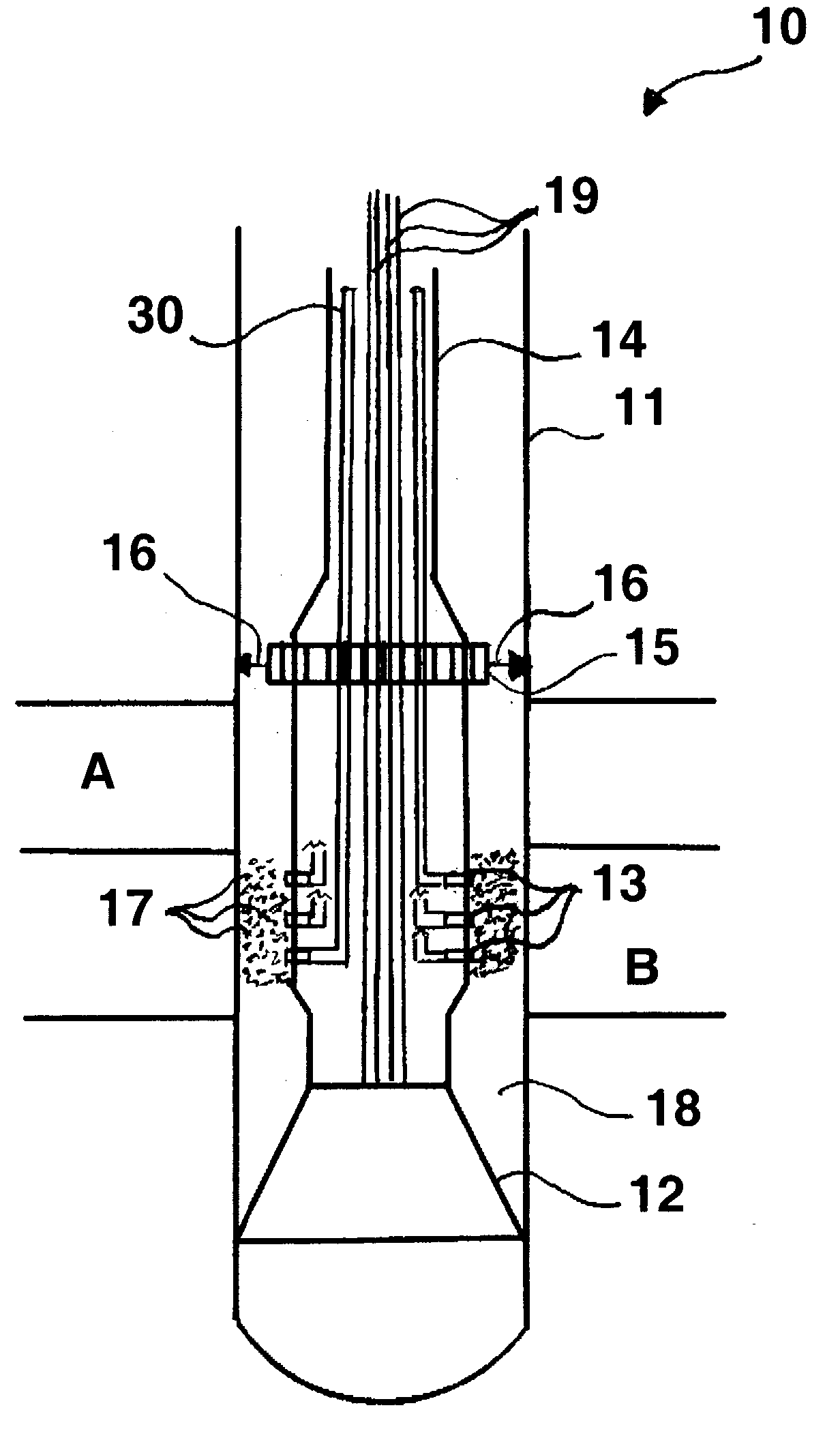
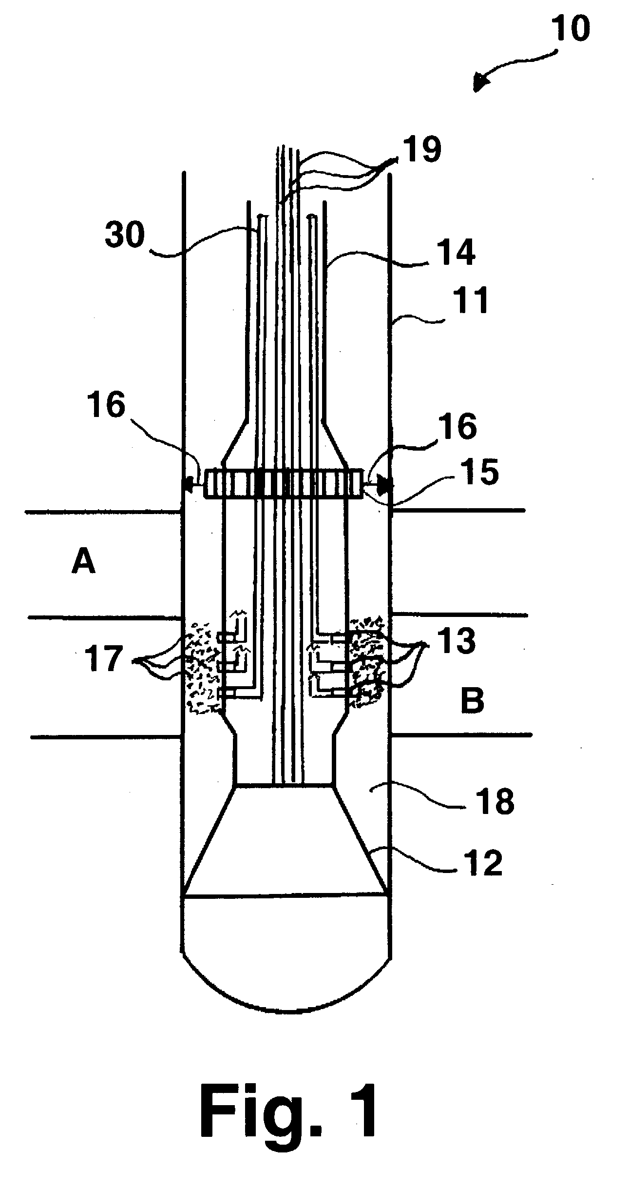
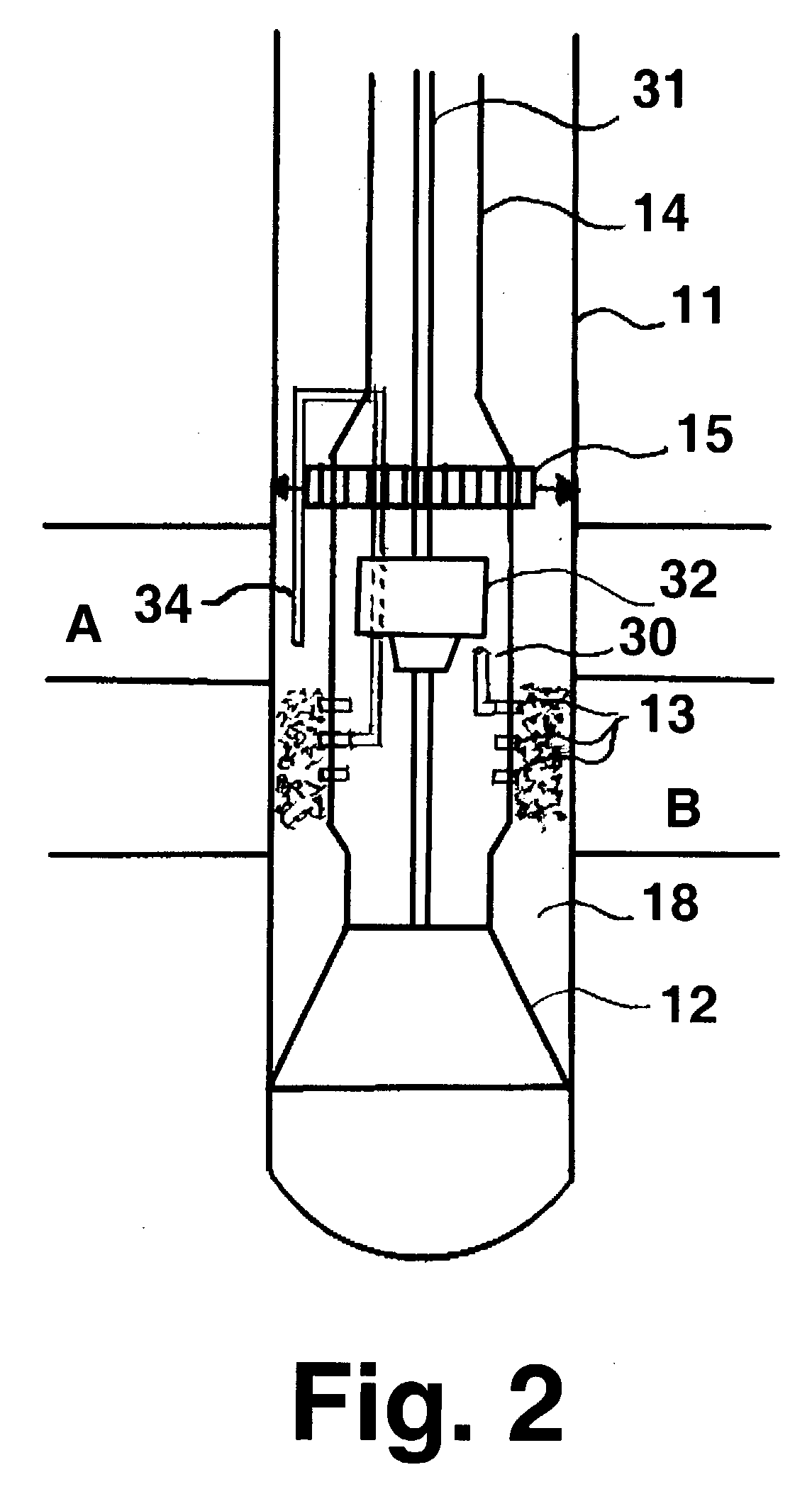
[0018] As previously stated, traditional oil well drilling requires the use of a drill casing liner to prevent sand production with the oil as it is retrieved from the ground by way of the well. In addition to the added financial burden on the drilling and production costs encountered when using these liners, there is also the added time required for installation. I have found that the use of drilling lasers in combination with fluid purging and / or cooling nozzles can accomplish the same objectives as a traditional liner, but in a much simpler and more efficient manner. Any combination of gas and / or liquid fluids that can provide control of the phases of the rock at in situ conditions may be employed for purging and / or cooling. Exemplary of such fluids are air, argon and liquid forms of gases, such as liquid nitrogen. In addition, water is kept out of the well and prevented from mixing with the oil as a result of the sealing over of the formations containing the water during the las...


PUM


Abstract

A method and apparatus for forming an in situ borehole liner in which a laser beam from a laser energy assembly disposed within a transparent drill head enclosure of a drill head assembly is directed into a rock formation to be drilled and a portion of the rock formation is melted, forming molten rock. The drill head assembly is directed into the molten rock forming a borehole having a borehole wall. At least one air stream from the drill head assembly is directed into the molten rock forming the molten rock against the borehole wall after which the molten rock against the borehole wall is cooled, forming a borehole liner.

Description

[0001] 1. Field of the Invention[0002] This invention is related to a method and apparatus for drilling wells using a drill head assembly employing laser energy assemblies as cutters. More particularly, this invention relates to a method and apparatus for drilling wells which produces a well or borehole liner in situ as the drilling operation progresses, thereby enabling the elimination of drill casing liners employed in conventional drilling operations.[0003] 2. Description of Related Art[0004] Traditional well drilling requires the use of drill casing liners when retrieving fluids such as oil to prevent the mixture of grains and particles with the fluid. These liners present an additional financial cost to the well completion operation, in addition to the time required to put them in place. Another problem associated with traditional drilling occurs when water is encountered in the formations being drilled. Keeping this water out of the well and preventing it from mixing with the ...

Claims


Application Information

Patent Timeline
IPC IPC(8): E21B7/14
CPCE21B7/14E21B33/138
Inventor BATARSEH, SAMIH
Owner GAS TECH INST
Why Eureka
Try Eureka