Car-mounted device control system

a technology of a control system and a driver's seat, which is applied in the direction of electric devices, non-deflectible wheel steering, underwater vessels, etc., can solve the problems of inadvertent operation of the above-mentioned devices, increased possibility of erroneous operation, and body of the vehicle occupant in the driver's sea

Inactive Publication Date: 2004-10-07
KK TOKAI RIKA DENKI SEISAKUSHO
View PDF7 Cites 39 Cited by
  • Summary
  • Abstract
  • Description
  • Claims
  • Application Information

AI Technical Summary

Problems solved by technology

In this case, depending on the mounted position and the like of the controller, the body of the vehicle occupant in the driver's seat (in particular, the palm or finger) interferes with the controller.
For this reason, there is the possibility that the aforementioned devices will be operated inadvertently.
Therefore, in the state in which the steering wheel is rotated, it is difficult to carry out a desired ...

Method used


Image

  • Car-mounted device control system
  • Car-mounted device control system
  • Car-mounted device control system

Examples


first embodiment

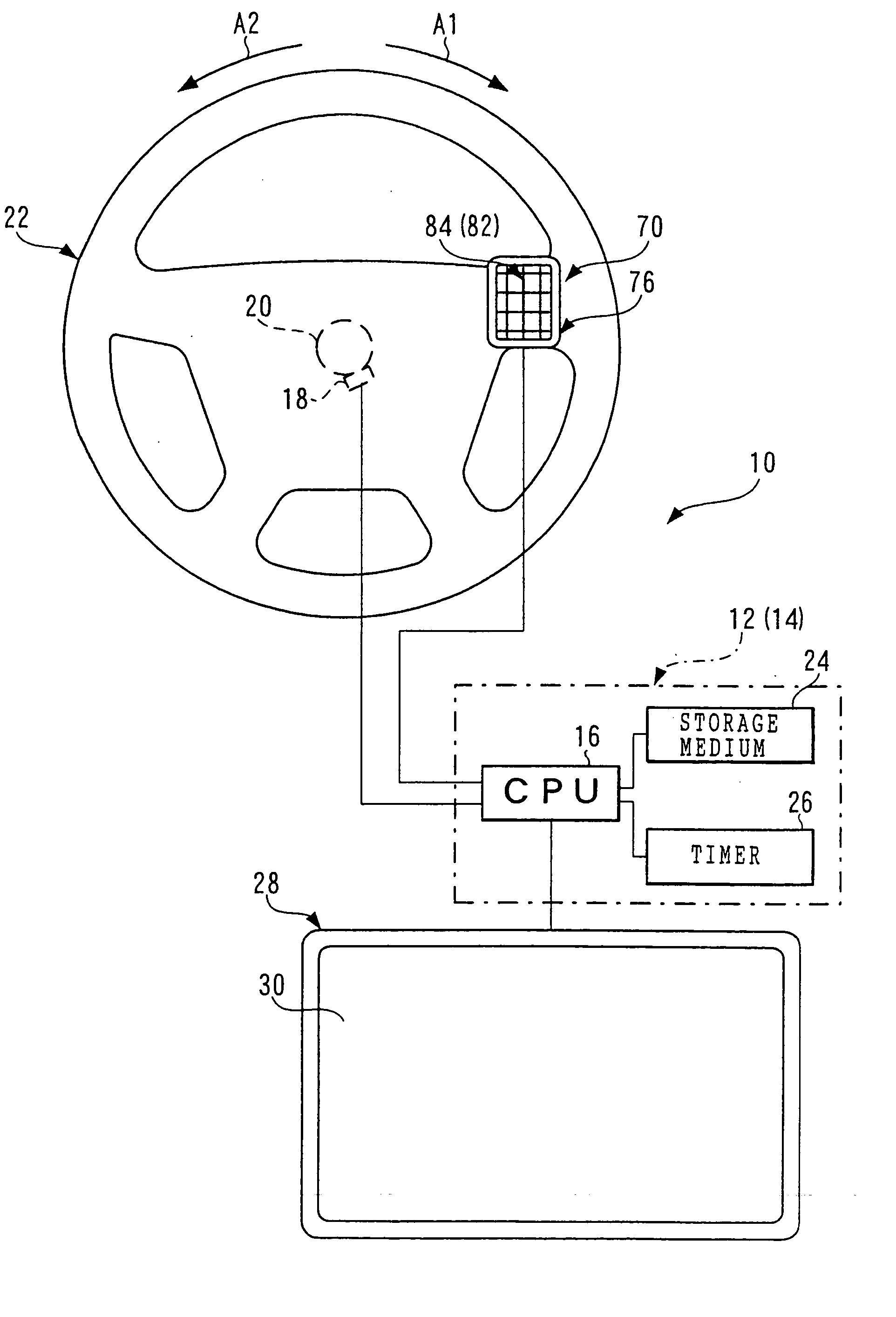
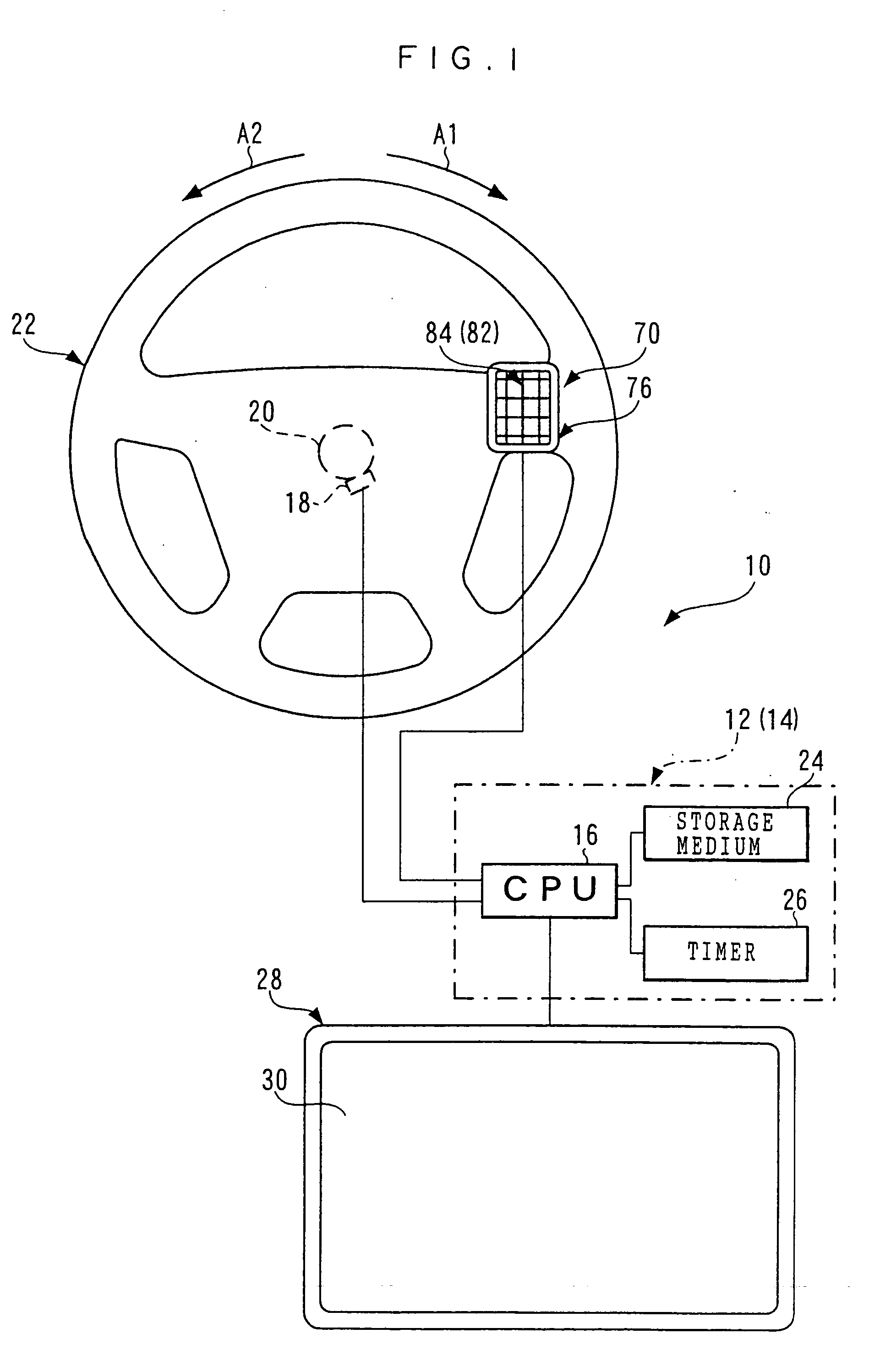
[0156] A summary of the structure of a center control unit 10, which serves as a car-mounted device to which is applied a car-mounted device control system relating to the present invention, is shown in a block diagram in FIG. 1.

[0157] As shown in this figure, the present center control unit 10 is equipped with a device main body 14 which is structured so as to include a computer 12 serving as a control means. The computer 12 is accommodated at the interior of the device main body 14 which is formed in a substantial box shape. Further, the device main body 14 is accommodated in an accommodating portion formed at the instrument panel of the car.

[0158] The computer 12 has a CPU 16. The CPU 16 is connected directly or indirectly to a steering angle sensor 18 which structures a rotation detecting means serving as a rotational position detecting means. The steering angle sensor 18 is provided in a vicinity of a steering shaft 20. A steering wheel 22 is connected coaxially and integrally ...

second embodiment

[0246] The summary of the structure of a center control unit 330, which serves as a car-mounted device to which is applied a car-mounted device control system relating to the present invention, is shown in a block diagram in FIG. 11.

[0247] As is shown in this figure, the present center control unit 330 is not equipped with the steering angle sensor 18 which was explained in the above-described first embodiment, and instead, is equipped with a rotational speed sensor 332. The rotational speed sensor 332 is provided in a vicinity of the steering shaft 20. The rotational speed sensor 332 detects the rotational speed (e.g., the angular speed) of the steering shaft 20 at the time when the steering shaft 20 rotates. On the basis of the detected rotational speed of the steering shaft 20, the rotational speed sensor 332 detects the rotational speed of the steering wheel 22. The rotational speed sensor 332 outputs an electrical speed detection signal (voltage or the like) corresponding to th...

third embodiment

[0256] A summary of the structure of a center control unit 400, which serves as a car-mounted device to which is applied a car-mounted device control system relating to the present invention, is shown by a block diagram in FIG. 15.

[0257] As shown in this figure, the present center control unit 400 has basically the same structure as the above-described first embodiment. However, differently from the above-described first embodiment, in the present center control unit 400, a correction program is stored in the storage medium 24.

[0258]

[0259] Next, the operation and effects of the present embodiment will be described on the basis of a schematic flowchart of a screen scrolling program shown in FIG. 16, among the illustrated car navigation functions.

[0260] The screen scrolling program shown in FIG. 17 is read from the storage medium 24 and is executed due to, for example, the function switching program being started up in step 226 of the flowchart of the main program shown in FIG. 7, an...


PUM


Abstract

A car-mounted device control system is obtained which can prevent or lessen erroneous operation of operating portions, switches, and the like during rotation of a steering wheel. When a CPU 16 starts up a function switching program from a storage medium 24 on the basis of an inputted touch signal, a present center control unit 10 compares a comparative rotational position R0 read from the storage medium 24 and a rotational position detection signal R from a steering angle sensor 32. As a result, when the rotational position detection signal R exceeds the comparative rotational position R0, a touch signal and a click signal are cancelled. Thus, inadvertent switching of functions due to a body touching a controller 70 while a steering wheel 22 is rotated can be prevented.

Description

[0001] The present invention relates to a car-mounted device control system for controlling a car-mounted device, which is mounted in a car, at an operating means such as a controller or the like which rotates integrally together with a steering wheel.BACKGROUND TECHNOLOGY[0002] In recent years, various types of devices, such as navigation devices and the like which display the current position and the like of a car on a monitor screen by a control means such as a computer or the like, have been mounted in cars.[0003] As for such various types of devices, the aforementioned devices can be controlled by operating a controller.[0004] On the other hand, it has been thought to mount the controllers of such various types of devices at the steering wheels of cars. In the case of such a structure, there is the merit that the operability improves because switches or the controller can be operated without removing the hands from the steering wheel.[0005] By the way, in a case in which such a...

Claims


Application Information

Patent Timeline
IPC IPC(8): B62D1/04B60K35/00B60K37/06B60R16/02B62D1/16G06F3/023G06F3/033G06F3/041
CPCB60K35/00B60K37/06B60K2350/928G06F3/023G06F3/0418B60K2370/782
Inventor NAGASAKA, CHIKAO
Owner KK TOKAI RIKA DENKI SEISAKUSHO
Why Eureka
Try Eureka