Micromachined relay with inorganic insulation

a micro-mechanical relay and inorganic insulation technology, applied in the direction of electrostrictive/piezoelectric relays, contact devices, electrical apparatus, etc., can solve the problems of high on-resistance, non-zero leakage current of mos analog switches, and inability to meet the requirements of many applications

Active Publication Date: 2004-10-07
ANALOG DEVICES INC
View PDF9 Cites 18 Cited by
  • Summary
  • Abstract
  • Description
  • Claims
  • Application Information

AI Technical Summary

Problems solved by technology

MOS analog switches have the disadvantage of non-zero leakage current and high on-resistance.
However, this arrangement is not acceptable for many applications.
The use of electromagnetic actuation limits the extent to which these devices can be miniaturized, and also results in higher power consumption than electrostatic actuation.
However, a disadvantage of the device is that the material of the insulating segmen

Method used


Image

  • Micromachined relay with inorganic insulation
  • Micromachined relay with inorganic insulation
  • Micromachined relay with inorganic insulation

Examples


Embodiment Construction

[0040] As mentioned above, FIGS. 4 through 15 illustrate a process for constructing an insulated micromechanical switch according to the concepts of the present invention.

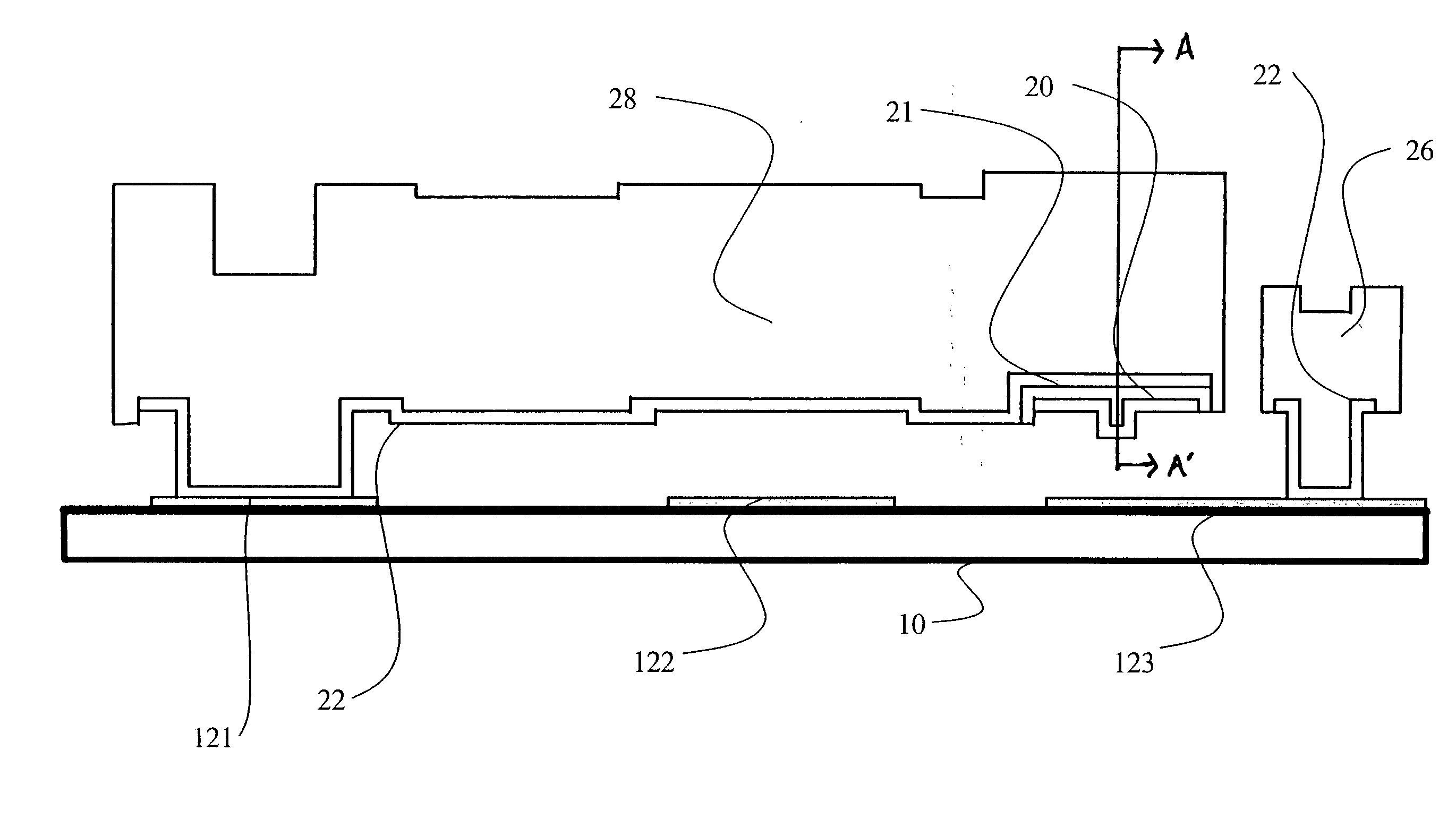
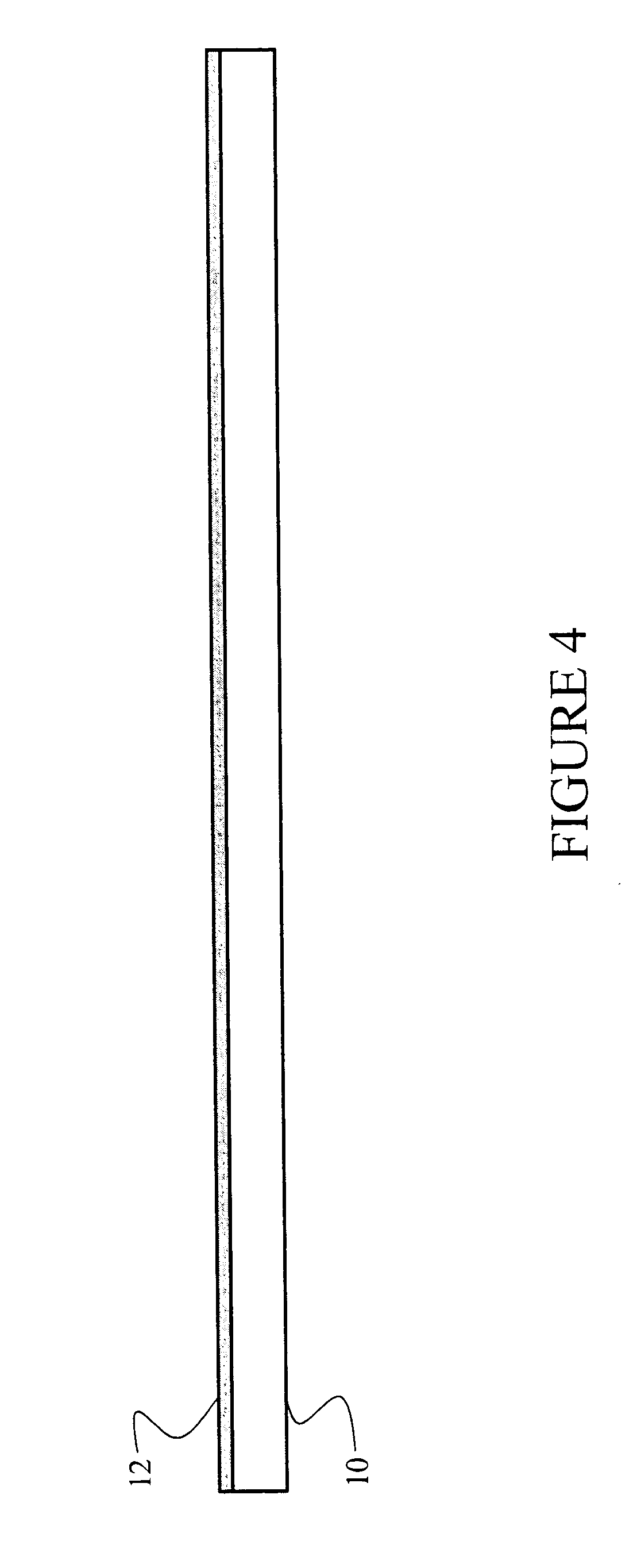
[0041] More specifically, as illustrated in FIG. 4, a substrate is coated, preferably by vapor deposition, with a metallic substance 12. The metallic substance 12 may be a metal from the group of platinum, palladium, titanium, rhodium, ruthenium, gold, or an alloy containing one of these metals. As illustrated in FIG. 5, certain portions of the metal layer 12 are stripped away by standard photolithographic patterning and dry etching techniques, so that electrodes or contacts 121, 122, and 123 are formed. Electrode 121 forms a source contact for the switch of the present invention. Moreover, electrode 122 forms a gate contact for the switch of the present invention. As illustrated in FIG. 16, the electrode 123 is actually a pair of electrodes 1232 and 1233 such that the switch makes an electrical contact between the...


PUM


Abstract

A micromechanical relay is made by surface micromachining techniques. It includes a metallic cantilever beam deflectable by an electrostatic field and a beam contact connected to the beam and electrically insulated from the beam by an insulating segment. During operation, the beam deflects, and the beam contact establishes an electrical contact between two drain electrodes.

Description

PRIORITY INFORMATION[0001] This application claims priority from provisional application Ser. No. 60 / 421,162 filed Oct. 25, 2002, which is incorporated herein by reference in its entirety.FIELD OF THE PRESENT INVENTION[0002] The present invention is directed to a micromechanical relay. More particularly, the present invention is directed to a micromechanical relay with inorganic insulation made utilizing micromachining techniques.BACKGROUND OF THE PRESENT INVENTION[0003] Electronic measurement and testing systems use relays to route analog signals. Switching devices used in these systems are required to have a very high off-resistance and a very low on-resistance. MOS analog switches have the disadvantage of non-zero leakage current and high on-resistance.[0004] One example of a prior art microswitch is illustrated in FIG. 1. The basic structure is a micromechanical switch that includes a source contact 14, a drain contact 16, and a gate contact 12. A conductive bridge structure 18 ...

Claims


Application Information

Patent Timeline
IPC IPC(8): H01H1/00H01H59/00
CPCH01H1/0036H01H59/0009
Inventor MAJUMDER, SUMITSKROBIS, KENNETHMORRISON, RICHARD H.
Owner ANALOG DEVICES INC
Why Eureka
Try Eureka