Reverberating mechanical siren

a mechanical siren and reverberating technology, applied in the field of reverberating mechanical sirens, can solve the problems of ineffective electronic sirens, achieve the effects of lessening the siren effect, improving the accurate reflectivity of rotors, and improving the effect of db values

Inactive Publication Date: 2004-10-14
GIEBELER JAMES FREDERICK
View PDF11 Cites 7 Cited by
  • Summary
  • Abstract
  • Description
  • Claims
  • Application Information

AI Technical Summary

Benefits of technology

0011] 1) A key feature of this application is the shape of the rotor passages, with their opposing angles and bottom slope to direct these rebounding sound waves back out through the intake throat. Because the reverberating sound wave is traveling at 10,700 feet per minute or 122 miles per hour, it follows the rule of opposite same angle rebound (like billiard ball). Each unnecessary rebound uses wave velocity and acoustic energy, lessening the sirens effect. These fast waves pass through the slower incoming air. Tests proved that the addition of the 45 degree ramps between the rotor blades, alone added 3 dB to the sound output.
0012] 2) Accordingly, it is another object of the present invention to smooth finish the rotor cast surfaces to improve the accurate reflectivity of the rotor. Again, tests of unfinished rotors showed spotty irregular dB readings, where as a smooth finished rotor produced a consistently higher dB value or a louder sound.
0013] 3) A further feature of this invention is the full height of the rotor blades, from the front ring to the hub base, which grab air from the central bore. Tests proved that the complete full height of these b...

Problems solved by technology

During the last 30 years improvements in automobile insulatio...

Method used


Image

  • Reverberating mechanical siren
  • Reverberating mechanical siren
  • Reverberating mechanical siren

Examples


Embodiment Construction

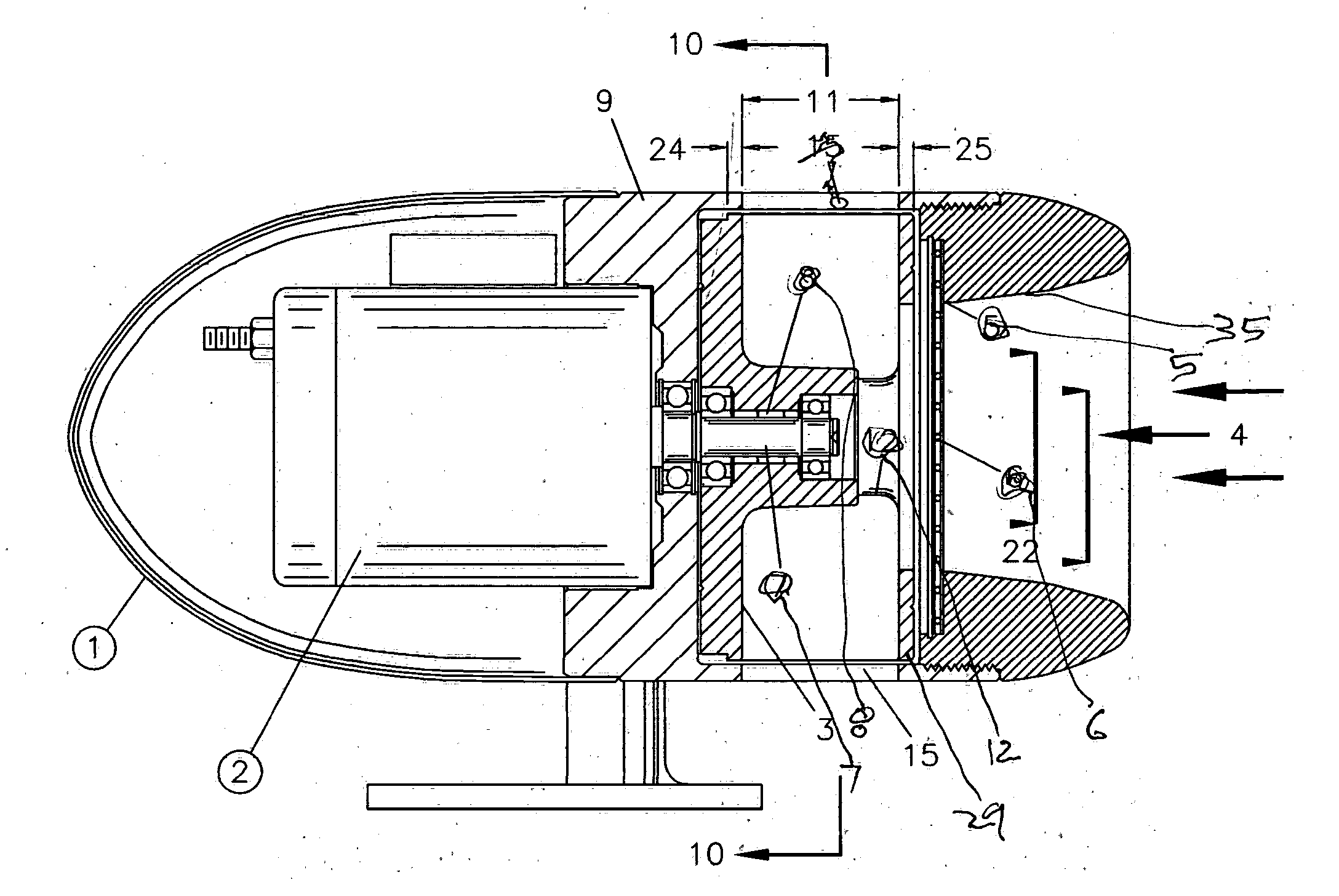
[0026] Referring to the drawings, FIG. 1 shows a mechanical siren assembly 1 which has an electric motor assembly 2 driving rotor 3 which pumps incoming air 4 from diverging nose 35 and throat 5 through screen 6. Said rotor 3 is driven in the clockwise direction by motor shaft 7 through a one-way roller clutch 8 in rotor 3. The rotor 3 is bearing mounted to shaft 7, to freely coast on said shaft 7 in stator 9 which is integral with the motor end bell.

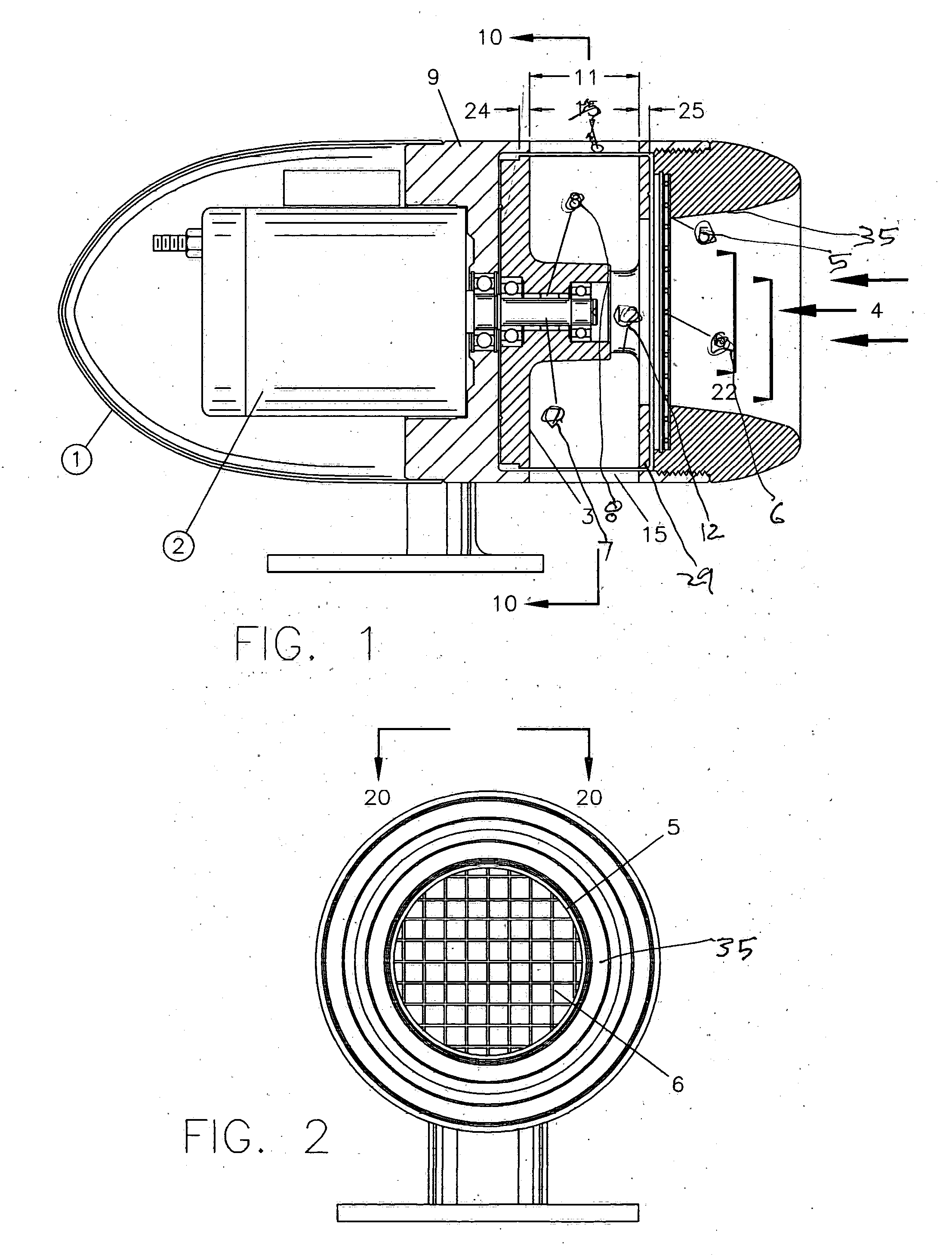
[0027] FIG. 2 is an end view of the siren 1 showing the diverging nose 35, throat 5 and screen 6.

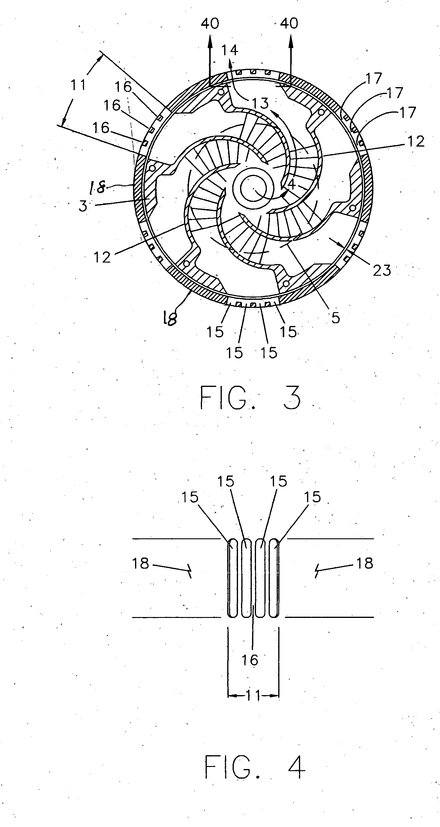
[0028] Now turning to FIG. 3, the sectional view shows rotor 3 with 6 blades. This typical siren has a pitch of 900 hz. A siren with a 5 bladed rotor would have a pitch of 750 hz. The pumping channels 12 of rotor 3 are shown aligned with the windows 11 allowing this accelerated air 13 to exit as exhaust 14 with the least possible resistance. This process might be liked to the siren's breathing. Window 11 is formed by a multiple of slots 15 w...


PUM


Abstract

A small light mechanical siren for mobile emergency equipment which utilize spiral rebound ramps in the rotor to produce a loud penetrating square form spiral sound wave enabling effective warning without contributing to noise pollution.

Description

BACKGROUND OF THE INVENTION AMENDMENTS[0001] Since the earliest days of mobile police, fire, and emergency medical services, mechanical sirens have helped to clear the way producing a particular whoo--whoo sound distinctly different from the bells, horns, and whistles of the other vehicles.[0002] The present invention makes the unique sound by rapidly momentarily turning on-off-on-off the air flow of its centrifugal air pump. These sirens were originally hand cranked, later driven by friction wheels against other rotating machinery, and still later by their own electric motor. In his 1925 U.S. Pat. No. 1,566,761 Miles disclosed an open rotor with straight pumping vanes radiating from the center with small right angle end flanges for closing the stator ports. In a subsequent U.S. Pat. No. 1,739,727 Miles demonstrates curved vanes and confirms that "as the air is forced outwardly and the ports are intermittently opened and closed by the rotor flanges a loud noise will be produced."[00...

Claims


Application Information

Patent Timeline
IPC IPC(8): G10K7/04
CPCG10K7/04
Inventor GIEBELER, JAMES FREDERICK
Owner GIEBELER JAMES FREDERICK
Why Eureka
Try Eureka