Liquid crystal display

a liquid crystal display and display panel technology, applied in the field of liquid crystal display, can solve the problems of low response speed, difficult to reproduce motion pictures, and inability of a general liquid crystal display panel to display half gray scales within a period of one frame, so as to prevent image degradation of the display image, and improve the image quality of the display image

Inactive Publication Date: 2004-10-14
SHARP KK
View PDF2 Cites 77 Cited by
  • Summary
  • Abstract
  • Description
  • Claims
  • Application Information

AI Technical Summary

Benefits of technology

0047] That is, according to the first invention configured as above, even when the detected temperature inside the device is unstable, it is possible to improve the image quality of the display image by variably controlling the emphasis conversion parameters in a stable manner.
0048] According to the second to the fifth inventions configured as above, based on the detected temperature for each partial area of the liquid crystal display panel, suitable overshoot drive for the input image data to be displayed in the partial area is implemented. Therefore, it is possi

Problems solved by technology

However, since the conventional LCDs are low in response speed, they have a drawback that it is difficult to reproduce motion pictures.
There has been a problem in that it takes long time to make a transition from a certain half gray scale level to another half gray scale level, so that it is impossible for a general liquid crystal display panel to display the half gray scales within the period of one frame (e.g., 16.7 msec. for a case of progressive scan of 60 Hz).
This not only produces afterglow but also hinders correct half gray scale display.
As a result, the image displayed on the liquid crystal display panel results in flickers and the like, degrading image quality.
Further, there are also cases where image quality is degraded due to temperature variation across liquid crystal display panel 4.
On the other hand, in the partial areas on liquid crystal display panel 4 where temperature is lower than the detected temperature of temperature sensor 16, excessive applied voltages of data (emphasis converted data) are applied possibly causing white spots and the like (when in the normally black mode), causing significant image quality degradation of the display image.
Resultantly, excessive applied voltages of data (emphasis converted data) may be supplied in partial areas, producing white spots, or insufficient applied voltages of data (emphasis converted data) may be su

Method used


Image

  • Liquid crystal display
  • Liquid crystal display
  • Liquid crystal display

Examples


first embodiment

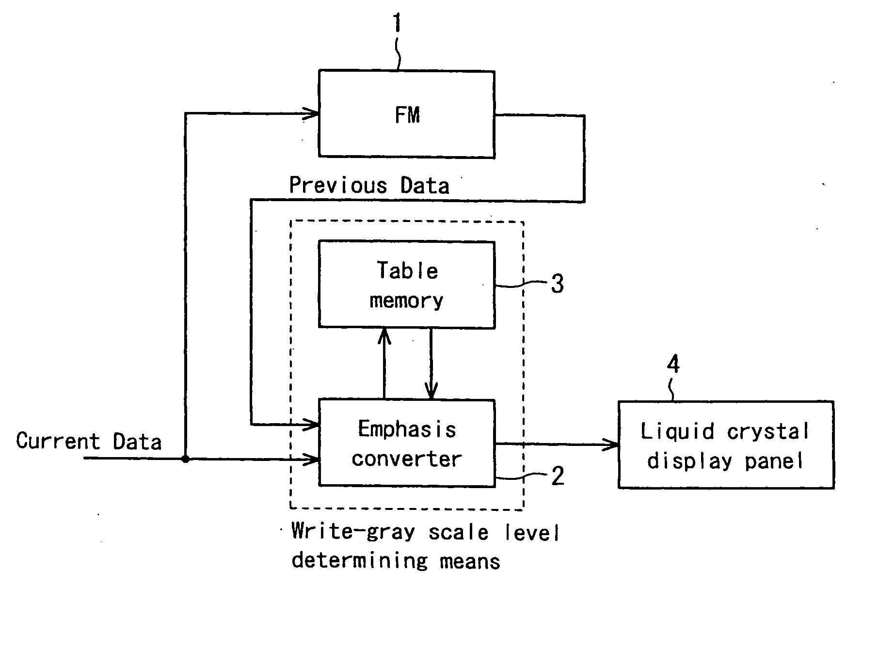
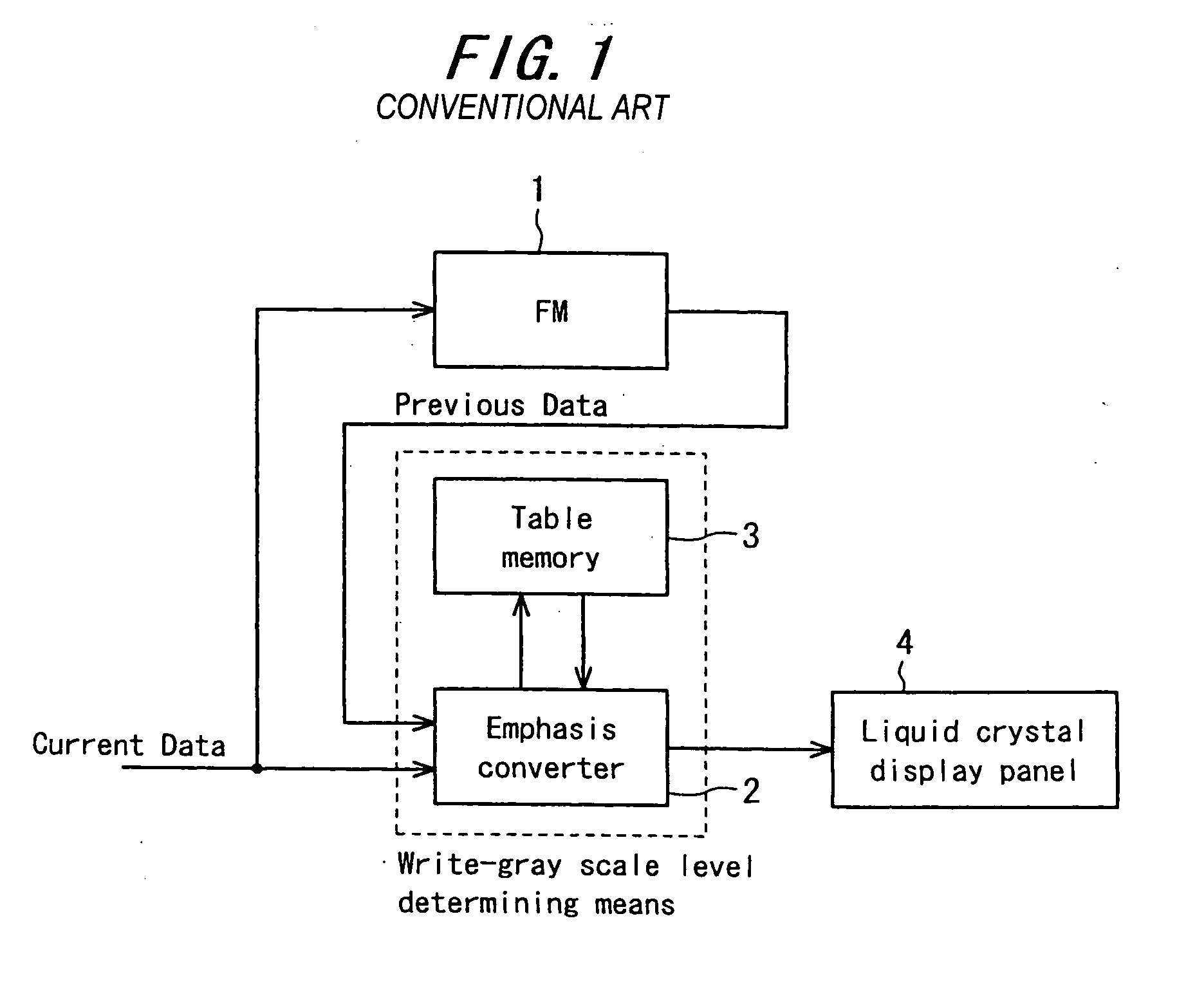
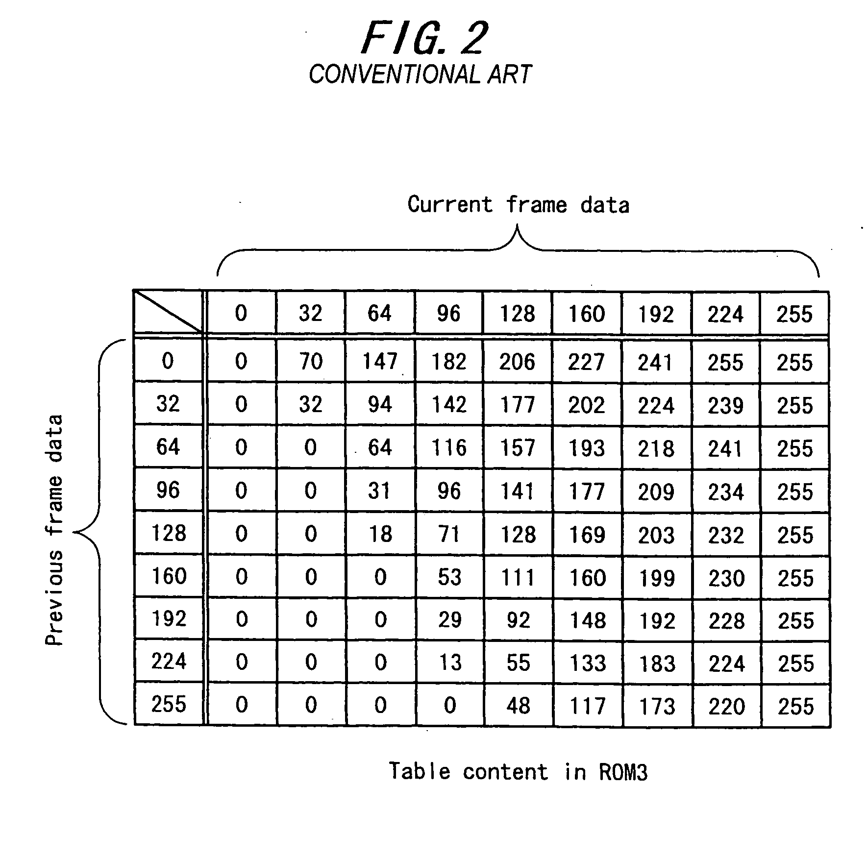
[0078] Now, the present invention will be described in detail with reference to FIGS. 7 to 10. Here, FIG. 7 is a block diagram showing a schematic configuration of essential components in a liquid crystal display of this embodiment; FIG. 8 includes schematic illustrative charts, showing table contents in ROMs in the liquid crystal display of this embodiment; FIG. 9 is an illustrative diagram showing the relationship between the detected temperature and the level at which the emphasis conversion parameter is switched in the liquid crystal display of this embodiment; and FIG. 10 is a flowchart showing a hysteresis process in the liquid crystal display of this embodiment.

[0079] In FIG. 7, 1 designates a frame memory (FM), 3 a table memory (ROM) storing emphasis conversion parameters in accordance with gray scale level transitions of input image data, 52 an emphasis converter which, by comparing the current frame image data with the previous frame image data read out from FM1 and readin...

second embodiment

THE SECOND EMBODIMENT

[0092] Next, the second embodiment of the present invention will be described in detail with reference to FIG. 11. Here, FIG. 11 is a flowchart showing a hysteresis process in the liquid crystal display of this embodiment.

[0093] The configuration of the liquid crystal display of this embodiment is identical with that of the first embodiment described above with reference to FIG. 7. The point of difference is in the hysteresis process in microcomputer 38, so description will be made as to this particular point with reference to the flowchart in FIG. 11.

[0094] First, the temperature data from thermistor 37 is acquired (Step S11). The current LEVEL for the emphasis conversion parameters corresponding to the obtained temperature data is determined (Step S12). The thus determined current LEVEL is compared with the determined LEVEL for the emphasis conversion parameters having been selected (Step S13). If both are equal, both the counter values on the up-counter and d...

third embodiment

THE THIRD EMBODIMENT

[0105] Next, the third embodiment of the present invention will be described in detail with reference to FIGS. 13 and 14. The same components as those in the conventional example are allotted with the same reference numerals and description for those is omitted. Here, FIG. 13 is a block diagram showing a schematic configuration of essential components in a liquid crystal display of the present embodiment. FIG. 14 includes schematic illustrative charts showing the table contents in table memories used in the liquid crystal display of the present embodiment.

[0106] This embodiment, as shown in FIG. 13, includes four temperature sensors 16a to 16d each detecting the panel temperature of different divided areas of a liquid crystal display panel 4, equally divided into four image areas. Here, the number of area divisions of liquid crystal display panel 4 is not limited to four, but obviously, the whole area may be equally or unequally divided into two or more areas eac...


PUM


Abstract

An emphasis converter 52 compares the image data of the current vertical period with the image data of the previous vertical period and controls the input image data to a liquid crystal display panel 4 based on the emphasis conversion parameters stored in tables of ROMs 3a to 3c so as to achieve accelerated drive. A microcomputer 38 is able to realize stable control of selecting emphasis conversion parameters by adding hysteresis to the detected temperature from a thermistor 37 even when the detected temperature fluctuates up and down crossing the temperature threshold.

Description

[0001] The present invention relates to a liquid crystal display for image display using a liquid crystal display panel, and in particular relates to a liquid crystal display wherein the optical response characteristic of the liquid crystal display panel can be improved.[0002] Recently, as personal computers and television receivers have become lighter and thinner, reduction in thickness and weight of display devices has also been wanted. In answer to such demands, flat panel type displays such as liquid crystal displays (LCDs) have been developed in place of cathode ray tubes (CRTs).[0003] An LCD is a display device which displays desired image data by applying electric fields across a liquid crystal layer having anisotropic dielectric constants, injected between a pair of substrates so that the strength of the electric fields is controlled to thereby control the amount of light passing through the substrates. Such LCDs are typical examples of handy flat panel type displays. Of the...

Claims


Application Information

Patent Timeline
IPC IPC(8): G09G3/36
CPCG09G3/3611G09G2320/0233G09G2320/0252G09G2320/0261G09G2360/18G09G2320/041G09G2320/106G09G2340/0492G09G2340/16G09G2320/0285G02F1/133
Inventor SUGINO, MICHIYUKIKIKUCHIOSAKA, TOSHIHIKOYOSHII, TAKASHISHIOMI, MAKOTO
Owner SHARP KK
Why Eureka
Try Eureka