Battery cover assembly having integrated battery condition monitoring

a battery condition monitoring and battery cover technology, applied in the field of batteries, can solve the problems of battery voltage in itself providing limited information as to battery status and performance, and no means to ascertain the status of the battery

Inactive Publication Date: 2004-10-28
MICROCHIP TECH INC
View PDF80 Cites 62 Cited by
  • Summary
  • Abstract
  • Description
  • Claims
  • Application Information

AI Technical Summary

Benefits of technology

0009] The present disclosure also provides a battery post cover for receipt on a battery having at least one battery post extending therefrom. The cover includes the terminal assembly discussed above and further includes a first surface having a terminal port, a second surface having a post port, and wherein the cover defines a closed chamber. A circuit board is received in the closed chamber, and the terminal assembly is received in the cover with the terminal extending out of the terminal port an

Problems solved by technology

In present day vehicle systems there is generally no means to ascertain the status of the battery beyond the alternator output voltage.
However, battery voltage in itself provides limit

Method used


Image

  • Battery cover assembly having integrated battery condition monitoring
  • Battery cover assembly having integrated battery condition monitoring
  • Battery cover assembly having integrated battery condition monitoring

Examples


Embodiment Construction

[0036] Referring now to the drawings, the details of specific embodiments of the invention are schematically illustrated. Like elements in the drawings will be represented by like numbers, and similar elements will be represented by like numbers with a different lower case letter suffix.

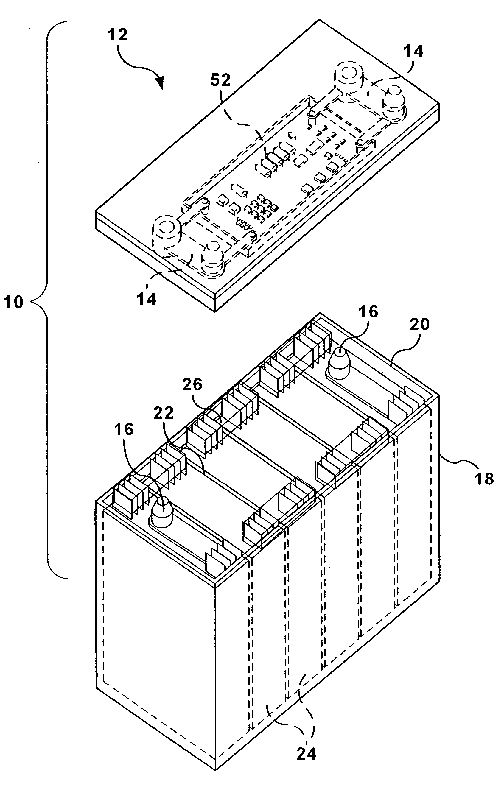
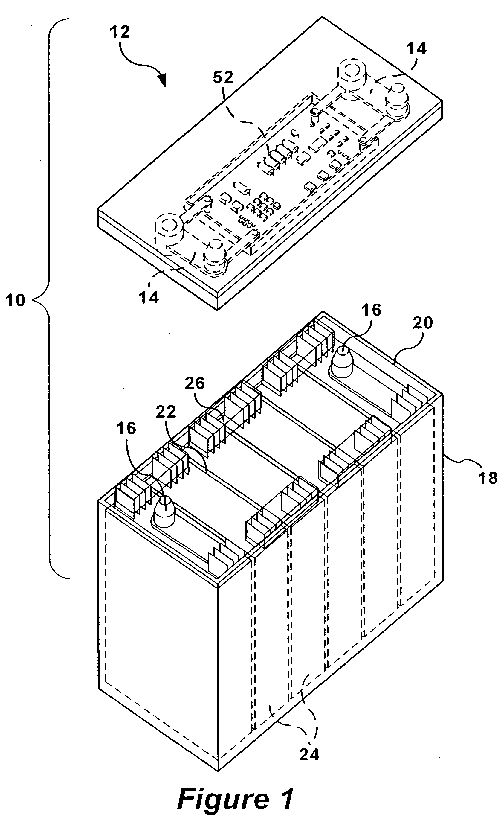
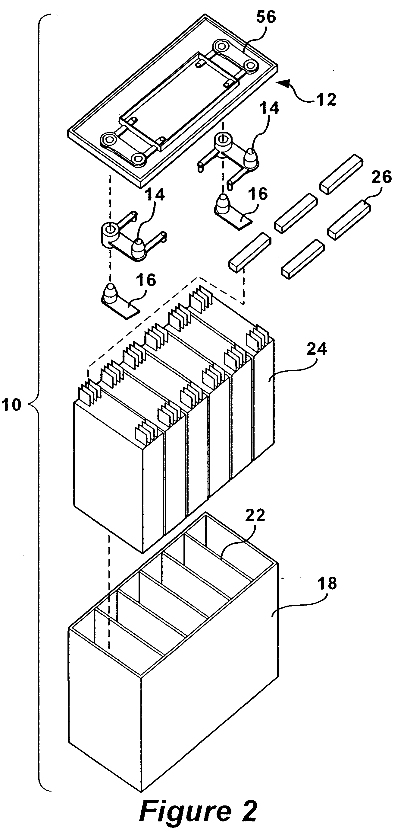
[0037] Referring to FIGS. 1 through 13, the present disclosure provides a battery 10 including a battery cover assembly 12 comprising terminal assemblies 14 adapted for the measurement of electrical current passing to and from posts 16 of the battery 10 and voltage therebetween, and a circuit board 52 used for monitoring the current and / or the voltage of the battery. The battery 10 is generally similar to typical lead-acid batteries used in powering vehicles, such as trucks, automobiles, motorcycles, and the like. It should be understood, however, that the present disclosure can be used with many different types of batteries other than lead-acid batteries, e.g., nickel metal hydride, lithium ion, and...


PUM


Abstract

A battery cover assembly having integrated battery condition monitoring for measuring electrical current passing to and from a battery post, including an electrically conductive collar for connecting to a post of a battery, and an electrically conductive terminal for receiving a connector of a load. An electrically conductive resistor having a known resistance extends between outer surfaces of the collar and the terminal. The battery cover assembly is incorporated into a battery, which may also include a voltage measuring device connected between the outer surfaces of the collar and the terminal for measuring the voltage drop across the resistor, memory for storing the known resistance of the resistor, and a digital processor programmed to receive the measured voltage drop from the voltage measuring device, retrieve the known resistance from the memory, and calculate current flow through the resistor based on the measured voltage drop and the known resistance, whereby current flow to and from the battery can be measured. A temperature measuring device may also be incorporated to measure temperature of the resistor located between the outer surfaces of the collar and the terminal. A resistance-temperature table may be stored in the memory and used to calculate the actual resistance of the resistor and then to compensate the current value from the voltage measured across the resistor.

Description

RELATED PATENT AND PATENT APPLICATION[0001] This application is a continuation-in-part patent application of commonly owned U.S. patent application Ser. No. 10 / 419,600, filed Apr. 21, 2003, entitled "A Battery Cover Assembly Having Integrated Battery Condition Monitoring" by David C. Batson, which is a continuation patent application of U.S. Pat. No. 6,628,102 B2, issued Sep. 30, 2003, which also claims priority to provisional U.S. Patent application Ser. No. 60 / 282,133, filed on Apr. 6, 2001, all of which are assigned to the assignee of the present patent application, and all of which are hereby incorporated by reference herein for all purposes.BACKGROUND OF THE INVENTION TECHNOLOGY[0002] 1. Technical Field of the Invention[0003] The present disclosure relates to batteries and, more particularly, to an integrated battery cover assembly having integrated battery condition monitoring. Even more particularly, the integrated battery condition monitoring includes current and voltage mon...

Claims


Application Information

Patent Timeline
IPC IPC(8): H02J7/00
CPCG01R31/3644H02J2007/0098H02J7/0047H01M10/4257Y02E60/10H02J7/0048H02J7/005
Inventor BATSON, DAVID C.
Owner MICROCHIP TECH INC
Why Eureka
Try Eureka