Display control device and display device

a control device and display technology, applied in the field of image display control devices, can solve the problems of inability to realize the function by hardware, the power consumption of the light source 32 cannot be suppressed without deteriorating the image quality, and the display capabilities of recent display devices have not necessarily reached an adequate level, etc., to achieve high-quality image display, the effect of increasing the light emission level of the display panel 31 and reducing the power consumption of the light source 32

Active Publication Date: 2004-10-28
PANASONIC CORP
View PDF2 Cites 13 Cited by
  • Summary
  • Abstract
  • Description
  • Claims
  • Application Information

AI Technical Summary

Benefits of technology

[0015] Thus an object of the present invention is to provide an image display control device, which can be realized readily in terms of hardware, can suppress flickering in image displays, and can suppress color clipping.

Problems solved by technology

However, the display capabilities of recent display devices have not necessarily reached an adequate level and measures are necessary for improving the apparent view-amenity better than the cases where input image signals are input as they are into a display device.
(Problem 1) Since the sigmoid function is nonlinear, it cannot be realized by a simple operational circuit.
It is therefore not practical in realizing the function by hardware.
However, in a case where pictures change in a continuous manner, this parameter tends to change greatly for every frame of picture and a flicker occurs in the displayed image after conversion.
Therefore, when a process of increasing the Y signal is performed without special consideration and then an inverse mapping from the Yuv color space to the RGB color space is performed, a result that exceeds the brightness component capacity of the RGB color space, that is, a result that cannot be displayed actually may be obtained.
Consequently, color clipping may occur.
However, when the color after the process in the Yuv color space is inversely mapped to the RGB color space, the result of B>100%, which cannot be displayed, is obtained, thus causing color clipping.

Method used


Image

  • Display control device and display device
  • Display control device and display device
  • Display control device and display device

Examples


embodiment 3

[0104] FIG. 6 to FIG. 8 concern an Embodiment 3. FIG. 6 is a block diagram of a display device of Embodiment 3 of the present invention.

[0105] In FIG. 6, a display unit 10 is the same as that of Embodiment 1. A display control device 50 has a weight-calculating unit 51.

[0106] The weight-calculating unit 51 applies a mask to an input image signal I0 in accordance with a weighting characteristic and outputs the masked signals to a characteristic value-calculating unit 21. Examples of the weighting characteristic are shown in FIG. 7 and FIG. 8. The characteristic value-calculating unit 21 calculates a characteristic value based on the masked input image signal.

[0107] With regard to this "mask," it is sufficient that the input image signal is masked in any way as a result. For example, I0*Weight(I0) may be used as the masked input image signal.

[0108] Besides this, a characteristic value-calculating unit 21 may obtain the characteristic value by dividing the product sum of the weight fac...

modification example 2

[0116] FIG. 15 concerns a Modification Example 2 of Embodiments 1 through 3. For simplification of description, the following description shall be based on Embodiment 1.

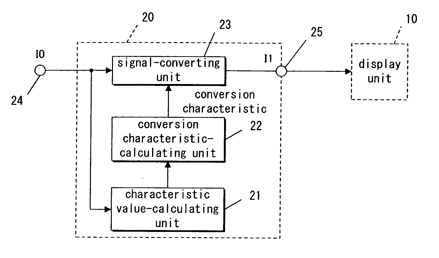
[0117] As shown in FIG. 15, according to Modification Example 2, a storage unit 29 is provided between an input terminal 24 and a signal-converting unit 23. The storage unit 29 is constructed, for example, by a memory and has a region in which an input image signal I0 for a single frame can be stored.

[0118] Providing the storage unit 29 is favorable in that a conversion characteristic, determined by a characteristic value-calculating unit 21 and a conversion characteristic-calculating unit 22 based on the input image signal I0 of an N-th frame (N being a natural number), can be applied to the input image signal I0 of the N-th frame itself.

[0119] When the circuit scale is restricted, the storage unit 29 may be omitted as shown in FIG. 1, FIG. 4, and FIG. 6.

modification example 3

[0120] FIG. 16 concerns a Modification Example 3 of Embodiments 1 through 3. As for Modification Example 2, a description based on Embodiment 1 shall be provided.

[0121] To put it simply, according to Modification Example 3, a characteristic value-calculating unit 21 calculates a plurality of characteristic values for an input image signal I0 of each single frame and display control is carried out based on these characteristic values.

[0122] In FIG. 16, a dividing unit 100 inputs an input image signal I0 of a single frame expressing a single image. The dividing unit 100 divides the single frame image into plural sub-images, each of the plural sub-images confined in an area. The dividing method is arbitrary. For example, if the input image signal I0 is in compliance with a format that enables distinction among objects, the dividing method may produce sub-images that indicate respective objects.

[0123] Also more simply, fixing the number of pixels and positions of a plurality of areas, t...


PUM


Abstract

A characteristic value-calculating unit, calculating a characteristic value based on an input image signal, a conversion characteristic-calculating unit, determining a conversion characteristic from the characteristic value, and a signal-converting unit, converting the input image signals in accordance with the determined conversion characteristic, are provided. The conversion characteristic has a low level region segment, which is close to the origin, a high level region segment, which is close to a full scale point, and a middle level region segment, which is positioned between the low level region and high level region, and the slope in the middle level region is set so as to be larger than both of the slopes of the low level region and the high level region.

Description

[0001] 1. Field of the Invention[0002] The present invention concerns an image display control device operable to provide improved feeling contrast for input image signals, and a display device utilizing the image display control device.[0003] 2. Description of the Related Art[0004] With the development of the information society, occasions in which users view images that are displayed on display devices are increasing. However, the display capabilities of recent display devices have not necessarily reached an adequate level and measures are necessary for improving the apparent view-amenity better than the cases where input image signals are input as they are into a display device.[0005] In regard to this, a reference 1 ("Gradation Conversion by a Sigmoid Function in a Digital Camera System," Watanabe et al., Japan Hardcopy 2000 Collected Papers B-27, The Imaging Society of Japan) proposes a method of using a sigmoid function to make black (low level) blacker, make white (high level...

Claims


Application Information

Patent Timeline
Patent Type & Authority Applications(United States)
IPC IPC(8): H04N5/20H04N9/64
CPCH04N5/20H04N9/646
Inventor KIUCHI, SHINYAIKEDA, JUNOJIMA, SHUICHIHIRASHIMA, TSUYOSHIHATA, RYOUTA
Owner PANASONIC CORP
Why Eureka
Try Eureka