RFID tag

Inactive Publication Date: 2004-11-04
ZIH CORP
View PDF7 Cites 139 Cited by
  • Summary
  • Abstract
  • Description
  • Claims
  • Application Information

AI Technical Summary

Benefits of technology

0003] It is the object of this invention to at least alleviate the disadvantages of the present systems, and those systems which may benefit from the addition of a battery, namely;

Problems solved by technology

the detrimental effect of incorporating a battery, on the physical characteristics, (such as flexibility, size and disposability) of the tag and;
the interference caused to the electrical and radio characteristics of the tag and its antenna which occurs when a battery is attached to a tag.

Method used


Image

  • RFID tag
  • RFID tag
  • RFID tag

Examples


Embodiment Construction

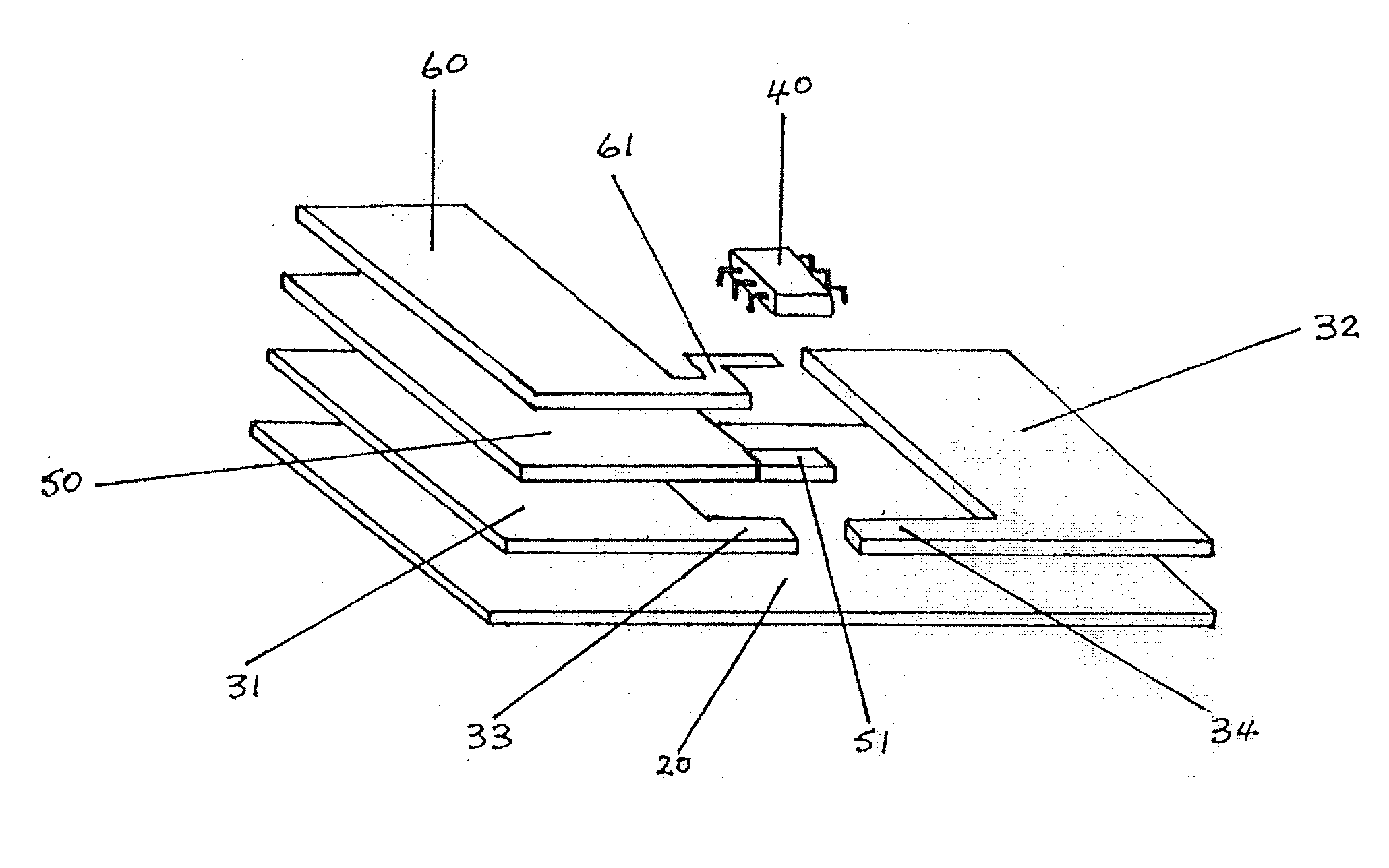
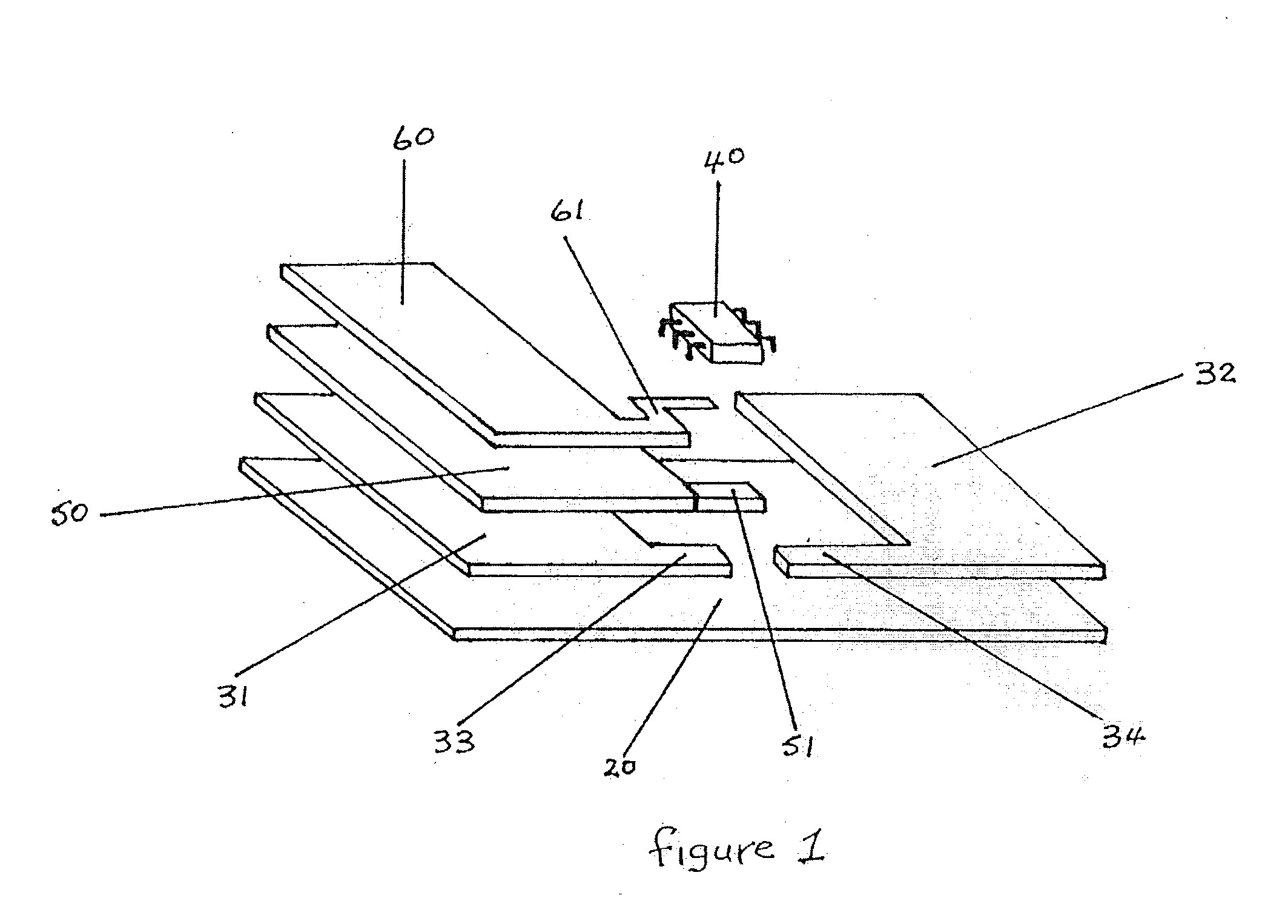
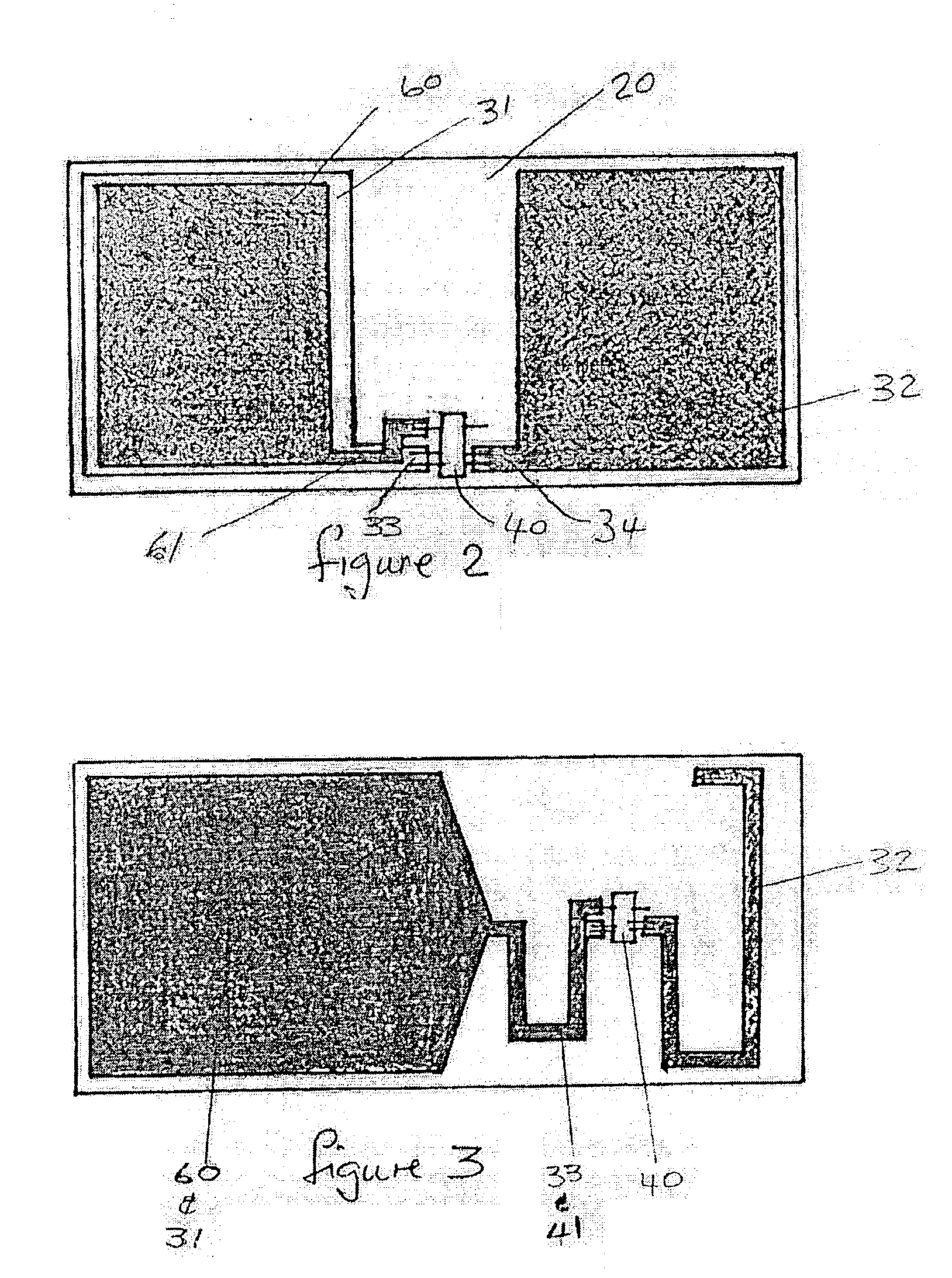
[0009] RFID tags usually (but not always) comprise an antenna which is formed of conductors; printed, plated, deposited or etched on a non-conductive substrate which may be flexible or rigid; to which is attached by means of solder or adhesives an electronic integrated circuit and optionally additional peripheral components. The antenna and integrated circuitry may also be formed on the integrated circuit itself, or spread over several insulating or semiconductor substrates. The conductors may be in the form of a dipole, loop, coil, zig-zag or patch antenna of types well known in the art. The antenna elements serve to collect radio frequency energy from the environment and conduct the energy to the integrated circuit, and to provide communication between the tag and the reader. The integrated circuit may have an external connection from its internal DC circuits to which a battery or other power source may be connected in order to provide the power necessary to operate the integrated...


PUM


Abstract

An RFID tag has a battery structure (31, 50, 60) and an antenna structure (31, 32) each sharing at least one common element (31) in order to minimise or eliminate the disadvantages normally associated with attaching a battery to a tag. A radio communication system comprising a reader and a plurality of RFID tags, and a method of fabricating the RFID tags are also described.

Description

[0001] This invention relates to radio (wireless) communication systems and more particularly to wireless communication systems using passive backscatter modulation technology. The invention also relates to an RFID tag and a method of fabrication.BACKGROUND TO THE INVENTION[0002] Radio Frequency Identification (RFID) systems are used for the identification and tracking of objects, people, goods and living things. RFID systems usually, but not always, comprise a reader also known as an interrogator and a plurality of transponders, usually called tags, which are attached to, integrated into or carried by the object to be identified and tracked. The reader in an RFID system will be a transceiver incorporating a transmitter and a receiver. The transmitter is used to send commands or data to tags; the receiver being used to receive and decode messages from one or more tags. Additionally if a tag does not have its own internal power source, the reader's transmitter energy field is used by...

Claims


Application Information

Patent Timeline
Patent Type & Authority Applications(United States)
IPC IPC(8): G01V15/00G06K19/07G06K19/077H01Q1/24H01Q1/38H04B1/59H05K1/16
CPCG01V15/00G06K19/0702G06K19/07749H05K1/16H01Q1/2225H01Q1/44
Inventor TURNER, CHRISTOPHER G.G.
Owner ZIH CORP
Why Eureka
Try Eureka