Air intake apparatus

a technology of air intake and air chamber, which is applied in the direction of combustion-air/fuel-air treatment, air cleaner and silencer combination, and separation process, etc., can solve the problems of low-frequency booming noise, special offensive to the ears of passengers in the cabin of the vehicle, and noise increase instead

Inactive Publication Date: 2004-11-18
TOYODA GOSEI CO LTD
View PDF7 Cites 27 Cited by
  • Summary
  • Abstract
  • Description
  • Claims
  • Application Information

AI Technical Summary

Problems solved by technology

The low-frequency booming noise occurs in a comparatively low engine speed.
The low-frequency booming noise is specially offensive to the ears of passengers in a vehicle cabin.
According to the air intake apparatus 100 disclosed in the same document, however, there is a fear that the noise increases instead due to the air-permeable member 112 in a comparatively high engine speed.
It is therefore difficult to bring about the effect of suppressing the intake noise due to the air-permeable member 112.
In addition, there is also a fear that the air-permeable member 112 itself vibrates due to the pulsating pressure of the intake air, and serves as a source of noise.
In such a manner, according to the air intake apparatus 100 disclosed in the same document, there is a fear that the noise increases with the increase of the transmitted noise when the engine speed is comparatively high.
On the other hand, intake noise leaks out from the inlet.

Method used


Image

  • Air intake apparatus
  • Air intake apparatus
  • Air intake apparatus

Examples


Embodiment Construction

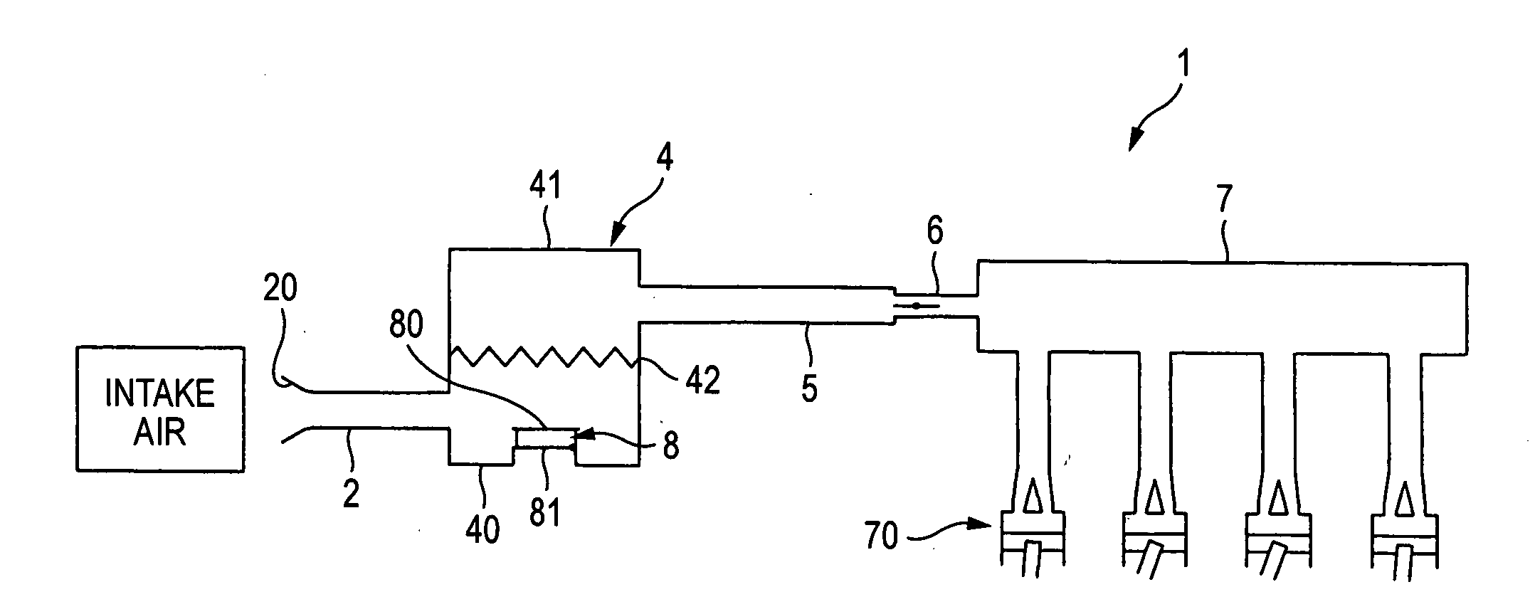
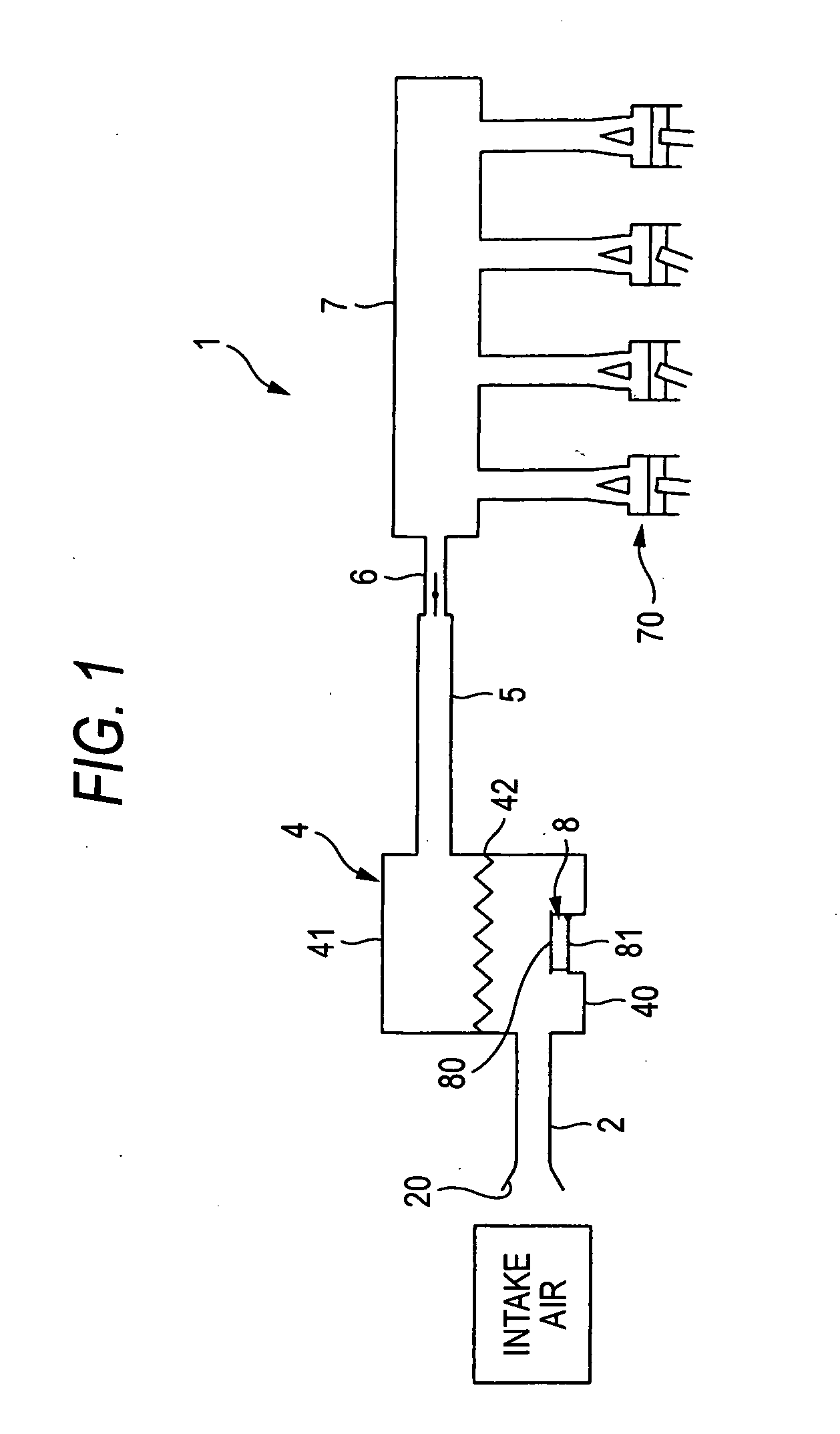
[0066] With reference to FIG. 1 again, description will be made below on experiments performed using the air intake apparatus according to the first embodiment. The air intake apparatus 1 according to the first embodiment is used as Example. In addition, an air intake apparatus in which only the air-permeable member 80 is disposed while the valve 81 is not disposed-is used as Comparative Example.

[0067] FIG. 6 shows the relation among the engine speed, the intake noise and the transmitted noise. In FIG. 6, the abscissa designates the engine speed (rpm). In FIG. 6, the ordinate designates sound pressure (dB). In addition, in FIG. 6, the solid lines (upper) designate intake noise data (thick line of Example and thin line of Comparative Example). In addition, in FIG. 6, the broken lines (lower) designate transmitted noise data (thick line of Example and thin line of Comparative Example).

[0068] Incidentally, the intake noise and the transmitted noise are measured as follows. That is, whi...


PUM

PropertyMeasurementUnit
frequencyaaaaaaaaaa
thicknessaaaaaaaaaa
pressureaaaaaaaaaa

Abstract

An air intake apparatus includes an air intake duct provided with an inlet through which intake air should be introduced, an air cleaner disposed on the downstream side of the air intake duct and for filtering the intake air, and an air cleaner hose disposed on the downstream side of the air cleaner and for supplying the filtered intake air to a combustion chamber of an engine, wherein an intake air passageway is laid out between the inlet and the combustion chamber. In a passageway wall surrounding an antinode of a lower resonance mode corresponding to the whole passageway length of the intake air passageway, a valve for opening a communicating path allowing the inside of the intake air passageway to communicate with the outside thereof at least when the lower resonance mode occurs, and an air-permeable member disposed to block the communicating path are disposed.

Description

[0001] The present application is based on Japanese Patent Application No. 2003-074933, which is incorporated herein by reference.[0002] 1. Field of the Invention[0003] The present invention relates to an air intake apparatus for supplying intake air to a combustion chamber of an engine.[0004] 2. Description of the Related Art[0005] FIG. 7 shows a schematic view of an air intake apparatus. As shown in FIG. 7, an air intake apparatus 100 includes an air intake duct 101, a resonator 110, an air cleaner 103, an air cleaner hose 104, a throttle body 105 and an intake manifold 106. The intake air is taken into the air intake duct 101 through an inlet 102, and supplied to a combustion chamber 109 of an engine through the resonator 110, the air cleaner 103, the air cleaner hose 104, the throttle body 105 and the intake manifold 106.[0006] Noise leaking from the inlet 102 (hereinafter referred to as "intake noise") becomes a problem in the air intake apparatus 100. The intake noise has a co...

Claims


Application Information

Patent Timeline
Patent Type & Authority Applications(United States)
IPC IPC(8): B01D46/10B01D46/52F02M35/024F02M35/14
CPCB01D46/10B01D46/4272B01D46/521B01D2279/60F02M35/024F02M35/14F02M35/02491F02M35/1222F02M35/1238F02M35/1255
Inventor KINO, HITOSHIHIROSE, YOSHIKAZUKOMORI, TAKAHIROSAWATARI, TOMOYUKI
Owner TOYODA GOSEI CO LTD
Why Eureka
Try Eureka