Communication apparatus, communication method and installation method of railway vehicle-facility intra communication system

a communication system and communication apparatus technology, applied in the direction of electric controllers, instruments, ignition automatic control, etc., can solve the problems of affecting the communication of power line carriers, generating substantial electromagnetic noise, and not considering the electric noise carried in the power line, so as to achieve good access to the vehicle and facilitate the passage of passengers

Inactive Publication Date: 2004-11-18
HITACHI LTD
View PDF3 Cites 30 Cited by
  • Summary
  • Abstract
  • Description
  • Claims
  • Application Information

AI Technical Summary

Benefits of technology

0007] The conventional technology shown in the reference 1 proposes the power line carrier communication using the trolley wire with the modulator / demodulator devices installed in the railway power substations and the railway vehicles. But no considerations are paid for these conventional technologies regarding the electric noises carried in the power line. The recent electric cars have various kinds of inverters to drive the power motors and to control devices that serve good accessibility of the vehicles and comfortableness for the passengers. The switching devices for these inverters, such as IGBTs (Insulating Gate Bipolar Transistor), bipolar transistors, FET (Field Effect Transistor) and thyristors, generate substantially the electromagnetic noise. The electromagnetic noise (we call EM noise, hereinafter) is generated by the inductance and the capacitance of the circuit and in the transient turn-on or turn-off switching of the switching devices. The frequency of the noises provided for the vehicle applications has been measured and it has been known that the frequency is from several hundred KHz to several tens MHz and sometimes to several hundred MHz in the high frequency range. The frequency of the electric power used for the driving motors is variable for the speed control and the EM noise less than several tens KHz is generated as well. The power distribution against the frequency is that the low frequency noise has more power than the high frequency noises. The frequency of EM noises in the inverter devices is mainly in less that several MHz. These noises are fed back to and superimposed in the power line. The discharge between the trolley wires and the pantograph generates EM noises in rather higher frequency as several MHz to several hundred MHz superimposed in the trolley wire. It has been found that these noises intrude in and disturb the power line carrier communication executed between the modulator devices and the demodulator ones attached to the railway cars and railway power substations. The trolley wire works as an antenna to receive radio waves used for the ham stations and TV and radio broadcast stations and repeater stations. These waves work as noises in the trolley wires and disturb the power line carrier communication as well.

Problems solved by technology

But no considerations are paid for these conventional technologies regarding the electric noises carried in the power line.
The switching devices for these inverters, such as IGBTs (Insulating Gate Bipolar Transistor), bipolar transistors, FET (Field Effect Transistor) and thyristors, generate substantially the electromagnetic noise.
It has been found that these noises intrude in and disturb the power line carrier communication executed between the modulator devices and the demodulator ones attached to the railway cars and railway power substations.
These waves work as noises in the trolley wires and disturb the power line carrier communication as well.
Therefore it is a problem that the construction cost for the radio communication system is potentially high.

Method used


Image

  • Communication apparatus, communication method and installation method of railway vehicle-facility intra communication system
  • Communication apparatus, communication method and installation method of railway vehicle-facility intra communication system
  • Communication apparatus, communication method and installation method of railway vehicle-facility intra communication system

Examples


first embodiment

[0041] The First Embodiment

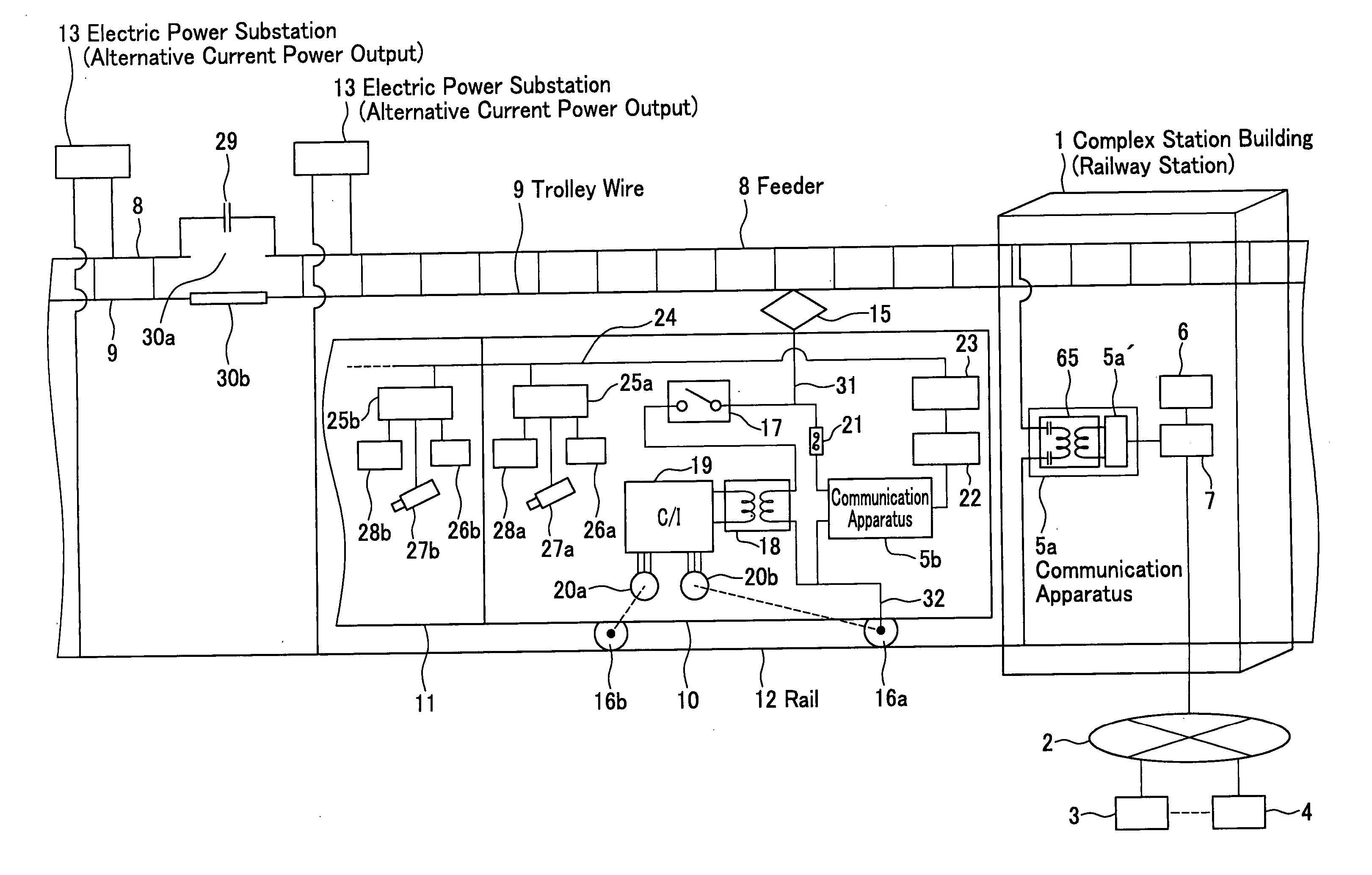
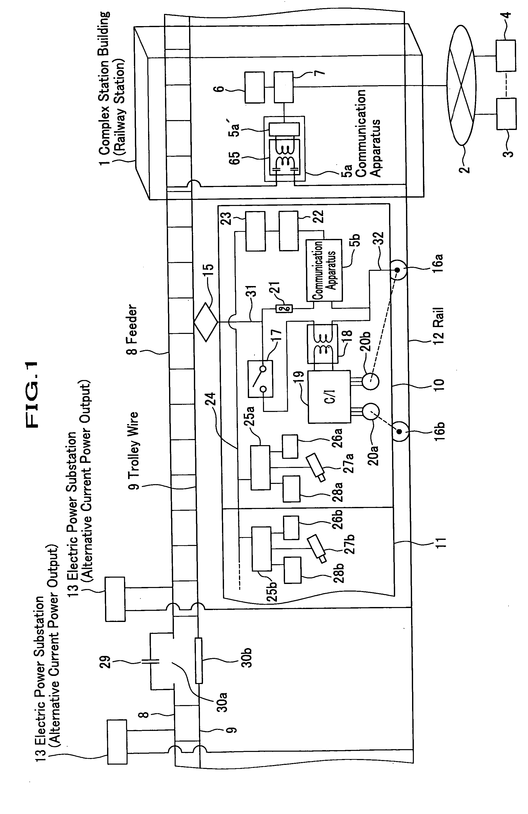
[0042] The FIG. 1 shows the first embodiment of the present invention for the railway vehicle-facility intra communication system. For the railway vehicle, an AC powered electric car is explained. The details of the complex building of the station are not drawn out, but the communication apparatus 5a is set in a maintenance factory and is connected to a server 7. The server is linked with a terminal device 6 as well as the communication network 2 through which advertisement center 3 and the reservation center 4 are connected thereto. The communication apparatus 5a is connected to the feeder 8 and the rail 12, both of which supply the electric power to the train. The train is formed with cars 10, 11 and etc. The car 10 receives electric power from the electric power substation 13 and 14 through a pantograph 15. The feeder supplies the electric power to the car 10 through a trolley wire 9 from the electric power substations 13 and 14. The trolley wire 9 func...

second embodiment

[0102] the present invention is explained by using FIG. 24, where a protocol conversion device is set between two feeders 8 which are isolated by the electric power substations 14. The portions common to those of FIG. 1 are shown in the same codes and are not explained again. The power supply capacity by an electric power substation 14 is limited by every several tens kilometers. The feeder 8 and trolley wire 9 are isolated from other interval to which an AC power is supplied by another electric power substation 14. The isolation is made by a spatial gap 30a between the feeders 8 and an isolator 30b. Therefore while the pantograph 15 is sliding onto the trolley line 9, the communication apparatus 5b cannot communicate with the communication apparatus 5a. In order to solve this problem, a pair of communication devices 33a and 33b is attached to the two isolated feeders 8 and an insulator 30b is set between the trolley wires 9. However the distance between the communication device 5b ...

third embodiment

[0103] the present invention is shown in FIG. 25, by which the communication apparatus 5b installed in the monorail electric car is explained. Two trolley wires 9a and 9b, to which DC electric power is supplied by electric power substation 13, are set on the surface of the concrete monorail 35. The electric power is supplied by two pantographs 15a and 15b from the trolley wires 9a and 9b. The communication apparatus 5b is connected to the pantographs and communicates with a communication apparatus 5b installed in a ticket control office or a train service office of the complex station building or the maintenance factory. The other portions of the system are same as those shown in FIG. 1. Since two trolley wires 9a and 9b are floating from the ground, the dielectric decay due to the water is suppressed in the communication. The two parallel trolley wires construct parallel communication lines where TEM (Transverse Electro-Magnetic) propagation mode dominates. Therefore the carrier si...


PUM


Abstract

A communication apparatus installed in the trains and that in a complex station building, a station or a maintenance factory communication through feeders, trolley wires or third rails can communicate each other. The present invention can realize a low cost vehicle-facility intra communication system that provides various information services available in the train.

Description

[0001] The present invention relates to an intra communication system to communicate necessary information between the railway vehicles and the railway facilities, especially, the communication apparatus, the communication method and the installation method.[0002] One of the recent services in the railway transportation services is a passenger information service available in the vehicles. For this purpose, a new communication cable is set along the railway and display panels are installed on the upper site of the car doors. In most cases, the information is provided by playback operation of the data that is retrieved from storage devices installed in the cars, but it is not on-line or real-time information. A recent demand for the technology is to provide the up to date information through a communication system that makes a linkage between the railway vehicles and the railway service facilities (we call this communication system as "a railway vehicle-facility intra communication s...

Claims


Application Information

Patent Timeline
Patent Type & Authority Applications(United States)
IPC IPC(8): H04B3/54H04J11/00H04B3/60H04J13/00
CPCH04B3/60
Inventor ARITA, SETSUOICHINOSE, YUJISHINMA, DAISUKEYAMADA, NAOYUKIAKIYAMA, HIROYUKIYANAI, SHIGENOBU
Owner HITACHI LTD
Why Eureka
Try Eureka