Method and device for machining annular-shaped workpieces

a technology of workpieces and methods, applied in the direction of connecting rod bearings, shearing apparatus, bearings, etc., can solve the problems of inconvenient use, relatively complex and non-economical methods, and insufficient finishing steps for bearings,

Inactive Publication Date: 2004-11-25
ALFING KESSLER SONDERMASCH
View PDF7 Cites 5 Cited by
  • Summary
  • Abstract
  • Description
  • Claims
  • Application Information

AI Technical Summary

Benefits of technology

[0023] As compared therewith, the invention achieves a high-quality end product with relative few method steps, wherein a microtoothing is formed across the whole fracture-splitting plane running through the workpiece and the plain-bearing layer, and wherein a regular joint having a high accuracy of fit and which does not need further finishing is particularly formed at the edge areas of the fracture-splitting plane meeting in the bore. Basically, the method according to the invention can be applied for workpieces which are equipped with only one single annular-shaped workpiece section as well as for workpieces which have a plurality of those sections arranged axially one behind the other or one beside the other. Thus, the method of the invention allows in a comparably simple, effective and very economical manner that workpieces are produced with a fracture-split annular-shaped workpiece section and a separated, fracture-split bearing of a high bearing quality and accuracy of fit which is arranged in this workpiece section. Complex finishing steps which would exceed the common finishing work of bearings are not required. As compared with conventional methods, this brings about a considerable cost reduction and, consequently, provides great rationalization possibilities.
[0029] The device according to the invention provides the same advantages as the method according to the invention already described above. In addition, the device according to the invention allows complex finishing devices to be dispensed with, as were hitherto necessary for conventional split bearings.

Problems solved by technology

Due to the required precision of the split bore and the workpiece sections at the partition line of the bore, these conventional methods are however relatively complex and non-economical.
Based on the high requirements generally made of bearings regarding rigidity and accuracy of fit, the production of split bearing constructions is in particular very complex.
These bearings further require considerable finishing steps.
Altogether, split bearing constructions are rather cost-intensive.
Contrary thereto, a method tested by the inventors for the purpose of a comparison, wherein the bearing material was first applied to an initial workpiece which was not fracture-split and wherein the workpiece was then fracture-split together with the bearing material layer in an operation process, did not provide satisfactory results.

Method used


Image

  • Method and device for machining annular-shaped workpieces
  • Method and device for machining annular-shaped workpieces

Examples


Embodiment Construction

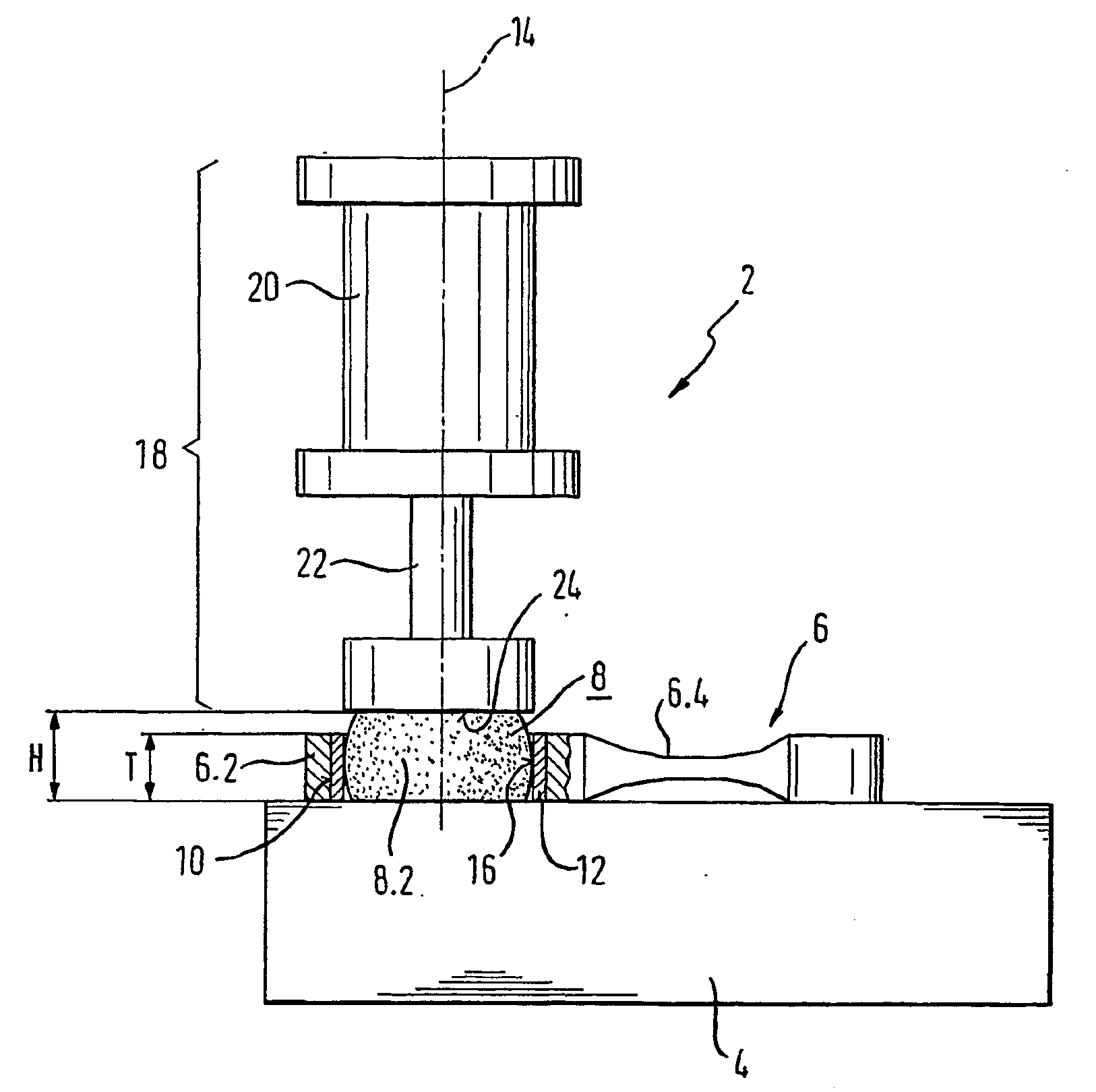
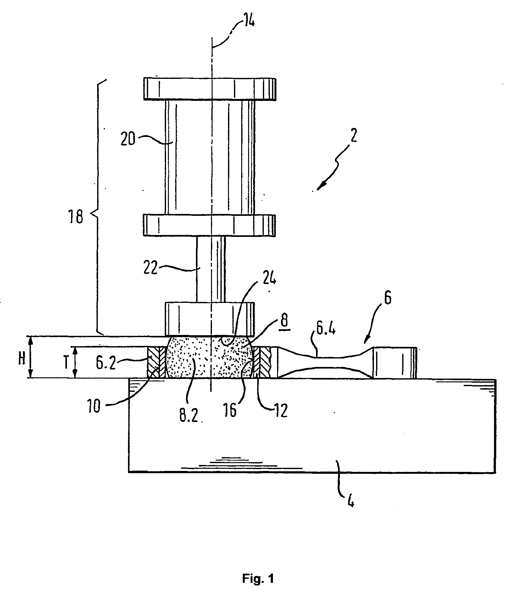
[0033] For the present description it is assumed that the workpiece to be machined by using the method of the invention is a prefabricated connecting rod billet having a not yet split connecting rod base with a bearing bore not yet split. In order that the connecting rod can be later fastened to a crankpin of a crankshaft and operated, the connecting rod billet must be split into two parts, namely into a connecting rod body and a connecting rod cover, in the area of the annular connecting rod base, which contains the bearing bore, and a plain-bearing material must be disposed in the bore. The bore which is not yet provided with the plain-bearing material is also designated below as basic bore.

[0034] The following steps are then performed for the above-indicated purpose, however, not inevitably in the given order.

[0035] At first, a pre-treatment of the connecting rod billet is carried out which contains the still not split connecting rod bore, and wherein the screw bores for the late...


PUM

PropertyMeasurementUnit
breaking pointaaaaaaaaaa
fracture-splitaaaaaaaaaa
areaaaaaaaaaaa

Abstract

The invention relates to a method and a device for machining workpieces comprising an annular-shaped section that is to be provided with a split bore. Said device comprises: a fracture-splitting device for fracture-splitting the annular-shaped workpiece section and for creating fracture-split workpiece parts corresponding with one another with a split bore; an applicator device for a plain-bearing material for applying at least one closed annular plain-bearing layer to the inner periphery of the split bore of the fracture-split workpiece; and fracture-splitting device for the plain-bearing layer for fracture-splitting the closed annular plain-bearing layer of the previously fracture-split workpiece.

Description

[0001] The present invention relates to a method and to a device for machining workpieces at least comprising an annular-shaped workpiece section that is to be provided with a split bore. Examples of such workpieces are connecting rods, annular-shaped housing sections or the like.PRIOR ART[0002] Methods are known in which workpieces having at least an annular-shaped workpiece section that is to be provided with a split bore (e.g. a connecting rod having a removable bearing cover) are manufactured by metal cutting. Due to the required precision of the split bore and the workpiece sections at the partition line of the bore, these conventional methods are however relatively complex and non-economical.[0003] For this reason, machining methods known as fracture-splitting methods and fracture-splitting devices have been developed, wherein the annular-shaped workpiece is provided with at least one preset breaking point and is split or a workpiece section is completely removed by means of a...

Claims


Application Information

Patent Timeline
Patent Type & Authority Applications(United States)
IPC IPC(8): B22F5/00B23P17/00B23D31/00B23P13/00F16C9/04
CPCB23D31/003Y10T29/49288Y10T29/53683Y10T29/49821F16C9/045F16C33/14B23P13/00
Inventor WISNIEWSKI, HORST
Owner ALFING KESSLER SONDERMASCH
Why Eureka
Try Eureka