Universal diagnostic method and system for engines

a universal diagnostic and engine technology, applied in the field of universal diagnostic methods and systems for engines, can solve the problems of difficult to identify faults in reciprocating-cylinder type engines, difficult to identify which cylinders are malfunctioning, and difficult to identify wha

Inactive Publication Date: 2004-11-25
ENGINES PDM
View PDF4 Cites 36 Cited by
  • Summary
  • Abstract
  • Description
  • Claims
  • Application Information

AI Technical Summary

Benefits of technology

0031] (c) monitoring the characteristics of the harmonic components of the Fourier representation at one or more predetermined frequencies according to one or more first predetermined criteria;
0032] (d) analysing the characteristics of the harmonic components obtained in step (c) according to one or more second predetermined criteria to determine the operational state of the engine correlated to said second criteria.

Problems solved by technology

U.S. Pat. No. 4,488,240], it has proved much more difficult to identify faults in reciprocating-cylinder type engines, the vibration characteristics of which tend to be more complex.
Whereas all these problems result in additional vibrations that can be detected by a suitable transducer or other detection means, and resolved using FFT or similar algorithms, in real engines with localised malfunctioning, it has proved difficult to identify which cylinder is malfunctioning, and what type of fault is present.
This is due to the complex nature of the reciprocating machines that incorporates a large number of moving parts.
Using known methods results in the generation of complex waveforms which do not easily lend themselves to advanced universal root cause analyses schemes and thus require massive accompanying references data bases that need to be recorded for each individual type of engine.
Due to the complexity that arises from the necessity to analyse the waveform, the system must be carefully adjusted to each engine type.
None of the above references provide a universal systematic method which is applicable for large numbers of engine, and in any case generally rely on comparison of the results obtained with a pre-acquired reference data base.
Furthermore, in this patent this analysis cannot be conducted at just one frequency, since an isolated peak without reference to the other two peaks is meaningless for providing multiples of f.

Method used


Image

  • Universal diagnostic method and system for engines
  • Universal diagnostic method and system for engines
  • Universal diagnostic method and system for engines

Examples


Embodiment Construction

[0218] Ford Champion Diesel Engine (2.5 L)

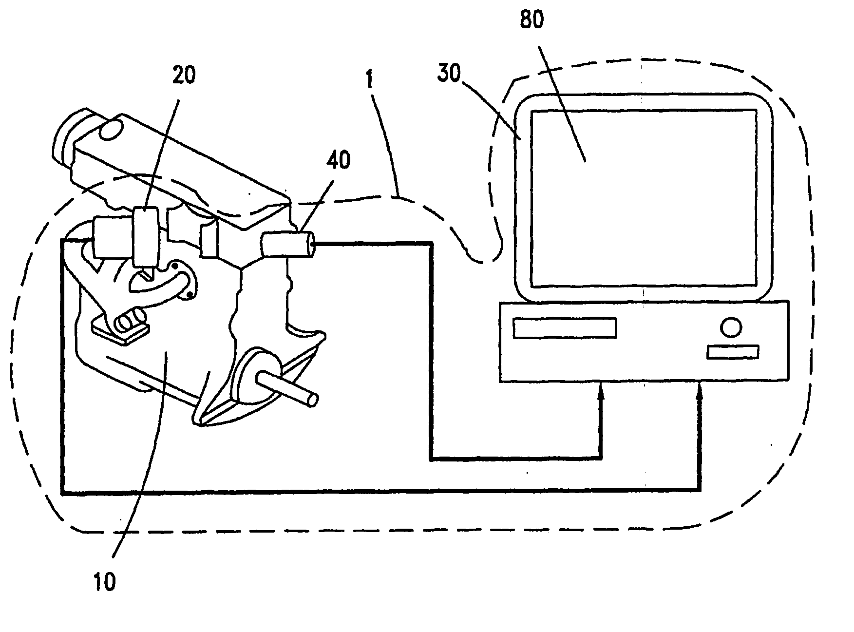
[0219] Experimental Set-Up

[0220] Vibration waveforms of a four stroke Ford Champion diesel engine were measured under various operating conditions. While the engine was not a brand new engine it was well maintained and in good condition. The acceleration transducer was mounted on the engine block and the acquired data was filtered with an antialiasing filter. A once per thermo-mechanical cycle trigger was obtained with a strain-gauge mounted on the fuel line from the primary fuel pump to the 3-rd cylinder. The combustion order of the engine is 3-1-2-4 and thus, in the following analysis, cylinder 3 is denoted as the first in the combustion sequence, cylinder 1 as the second one in the sequence and so forth.

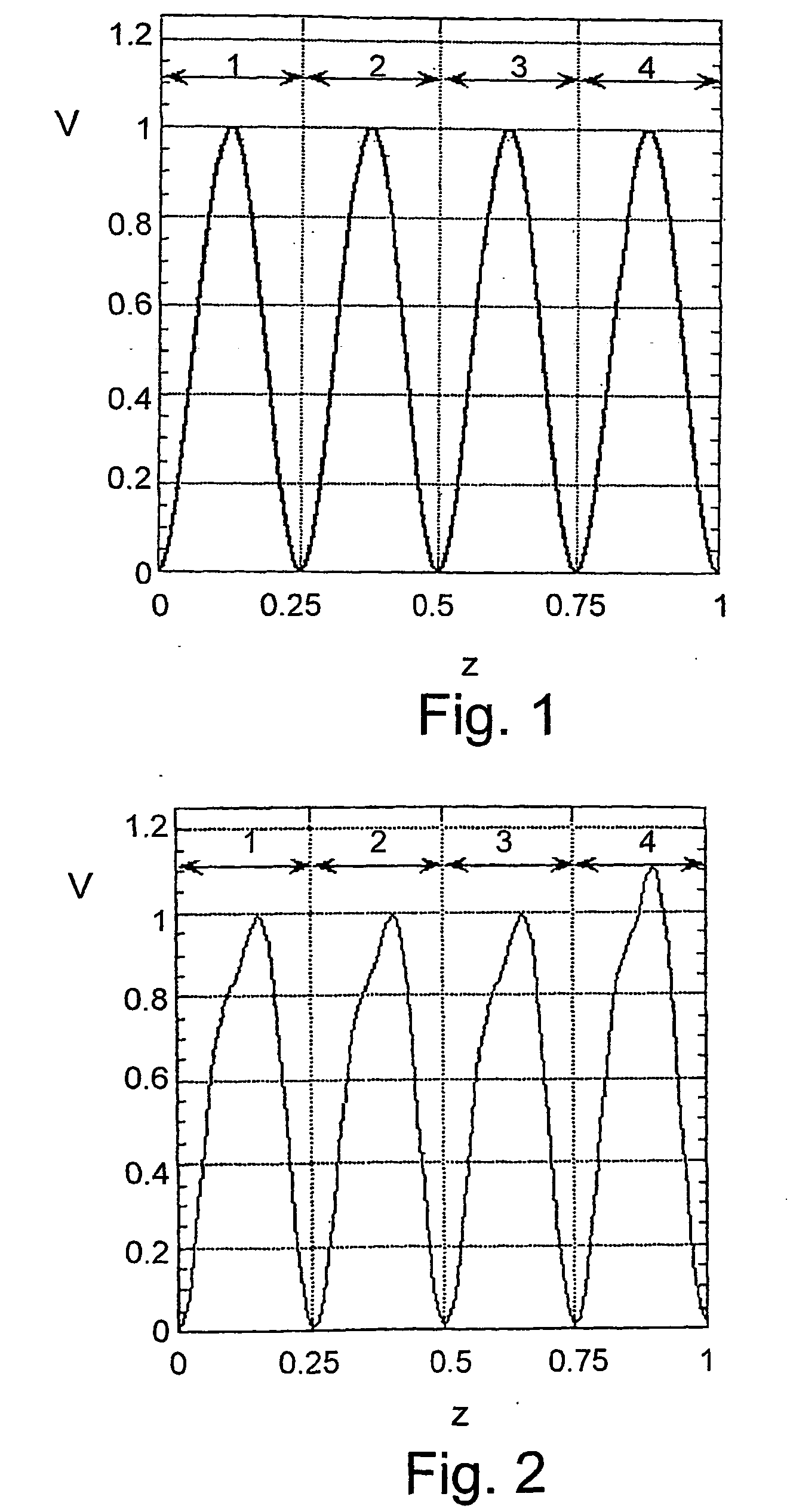
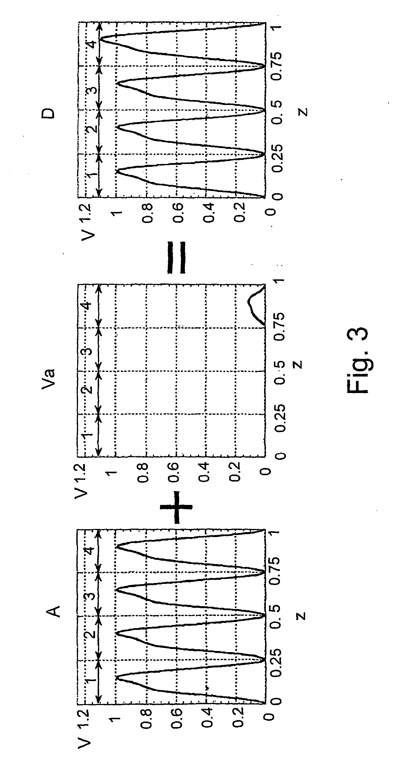
[0221] Synchronization Sequence and FFT

[0222] After the vibration data was acquired, the time interval between two consecutive fuel injections was divided into a fixed number of equally spaced sub-intervals. By application of a simple inte...


PUM


Abstract

A method and system are provided for diagnosing the health-condition of engines, in particular internal combustion reciprocating engines, in which the harmonic terms of the Fourier series representation of the engine vibration are correlated with the mechanical state of the engine. In particular, the characteristics of the harmonic components of the Fourier representation are monitored at one or more predetermined frequencies according to at least one first predetermined criterion, and the characteristics of these harmonic components are analysed according to at least one second predetermined criterion to determine the operational state of the engine correlated to the second criterion.

Description

[0001] The present invention relates to a method and system for the diagnosing and monitoring the operational state of engines, specially of reciprocating engines and in particular of internal combustion reciprocating engines.[0002] Reciprocating engines are widely used as a convenient means for converting chemical energy into motion. Several approaches have been proposed for diagnosing the state of health of such engines, and one of the most popular is by vibration analysis. Perhaps in its most basic form, an experienced maintenance technician or operator may often sense that something is wrong by the sound of an engine, aurally detecting undesirable vibrations. In certain circumstances, particularly with the more serious problems, he may even be able to isolate, or at least guess at the probable cause.[0003] More sophisticated and much more sensitive techniques for monitoring the health of an engine involve the detecting of the vibrations generated in operation, usually by use of ...

Claims


Application Information

Patent Timeline
Patent Type & Authority Applications(United States)
IPC IPC(8): G01M15/12
CPCG01M15/12
Inventor DEBOTTON, GALSHER, ERAN
Owner ENGINES PDM
Why Eureka
Try Eureka