Method of forming barbs on a suture and apparatus for performing same

Active Publication Date: 2004-12-02
CILAG GMBH INTERNATIONAL
View PDF98 Cites 86 Cited by
  • Summary
  • Abstract
  • Description
  • Claims
  • Application Information

AI Technical Summary

Problems solved by technology

However, such methods have not been commerci

Method used


Image

  • Method of forming barbs on a suture and apparatus for performing same
  • Method of forming barbs on a suture and apparatus for performing same
  • Method of forming barbs on a suture and apparatus for performing same

Examples


Embodiment Construction

[0043] We refer now to the drawings in detail wherein like numerals refer to like elements throughout the several views.

[0044] The purpose of the present invention is to provide for an effective way of producing a barbed suture. In this regard, several different types of methods are disclosed which are directed to the cutting action of a blade on the suture to create the barbs. As will be described, the cutting action envisioned takes into account the movement of the blade and the blade geometry.

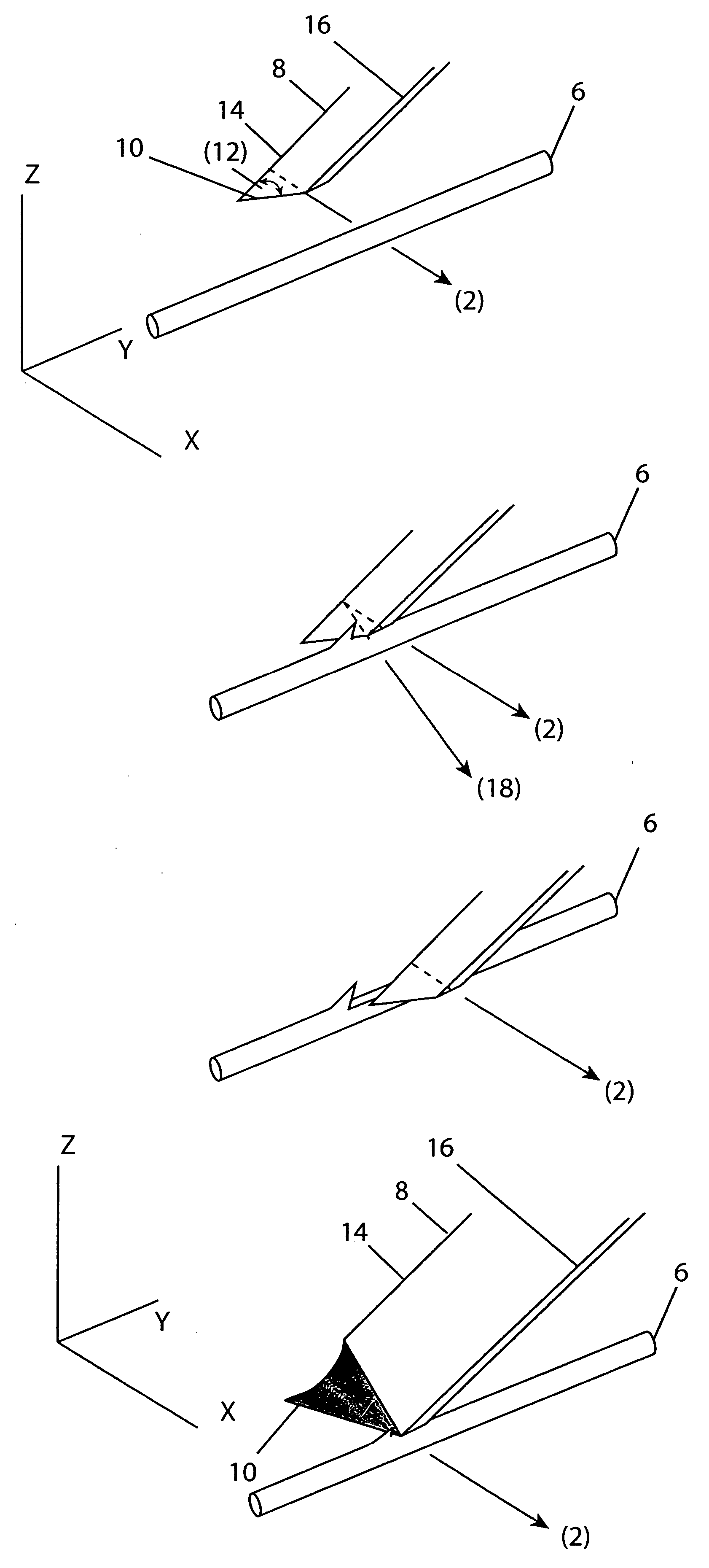
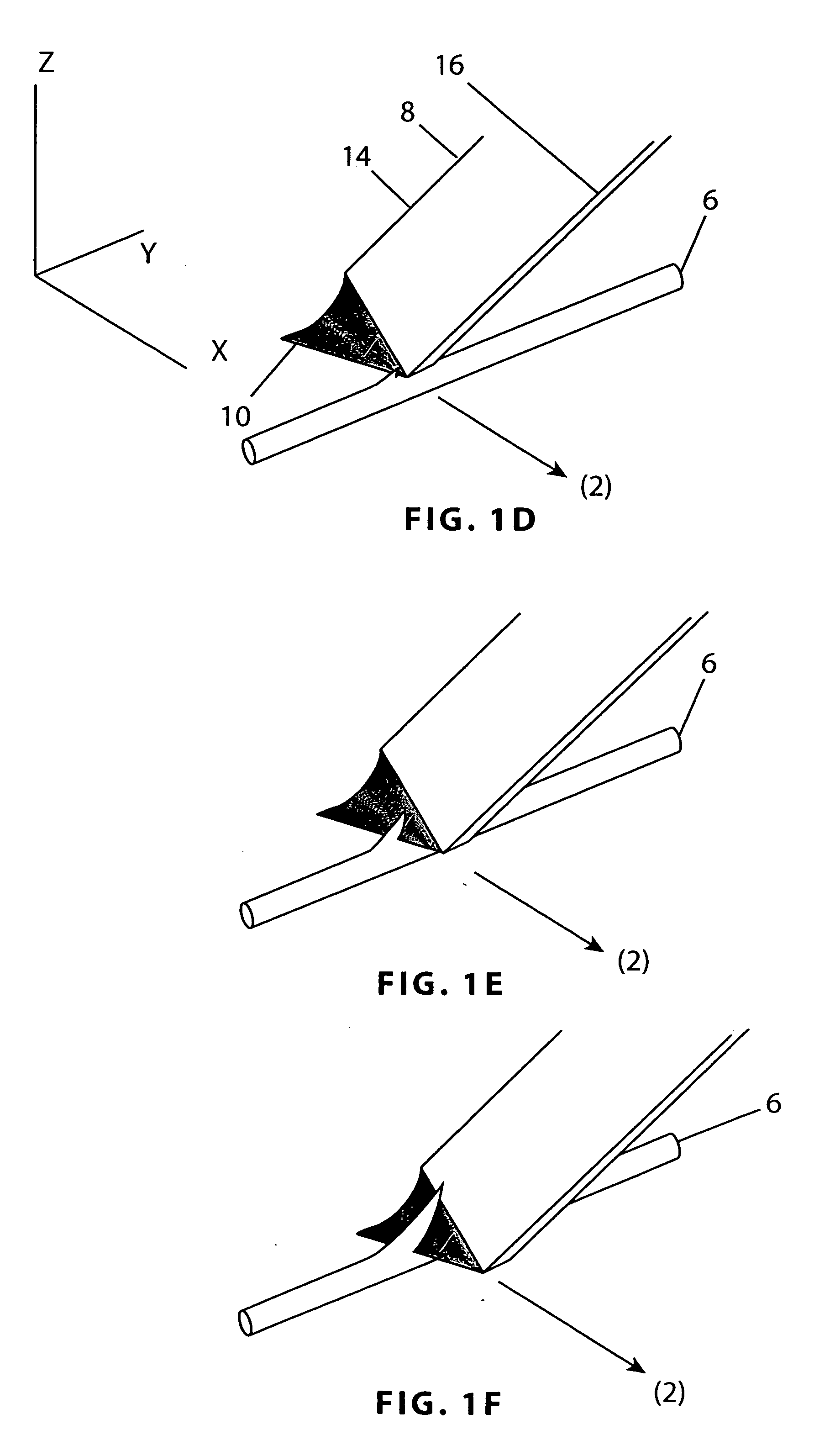
[0045] Essentially, the cutting of the suture with a blade takes into account three dimensions x-y-z of the suture 6. Each dimension is important and may be addressed by the cutting motion of the blade and / or the blade geometry. Depending on the blade geometry, the blade movement can have an effect in the other dimensions.

[0046] In this regard, FIG. 1A illustrates a consistent cutting motion of a blade 8 with one degree of freedom of movement and two degrees of freedom from blade geometry ac...


PUM

PropertyMeasurementUnit
Angleaaaaaaaaaa

Abstract

A method of making a barbed suture by varying the blade geometry and/or the movement of the blade when cutting a suture is disclosed. The method can also be accomplished with a cutting device to create a plurality of barbs on the exterior of surgical suture. The barbs produced using the method with the cutting device can be the same or random configurations.

Description

[0001] 1. Field of the Invention[0002] The invention relates to a method of barbing suture filament by varying the blade geometry and / or the movement of a blade when cutting a suture filament where the method can also be utilized to cut a plurality of axially spaced barbs on the exterior of sutures and an apparatus for performing this.[0003] 2. Description of the Prior Art[0004] In the prior art, it is well known that surgical and traumatic wounds are typically closed with a filament introduced into the tissue by a needle attached to one end. Closure of the wound and holding tissues together supports healing and re-growth. What is typically used for this procedure is known as a suture.[0005] A barbed suture is a one-way suture which allows passage of a needle-drawn suture in one direction through tissue, but not in the opposite direction. A barbed suture is generally an elongated body having a pointed leading end and a plurality of axially and circumferentially spaced barbs on the e...

Claims


Application Information

Patent Timeline
IPC IPC(8): A61B17/04A61B17/00A61B17/06A61B17/064
CPCA61B17/06166A61B17/064Y10T29/20A61B2017/06176B26D3/08A61B2017/00526Y10T83/0385Y10T83/4607Y10T83/896Y10T83/02Y10T83/202Y10T83/0333Y10T83/04Y10T83/0341B21J5/068A61B17/06
Inventor GENOVA, PERRY A.WILLIAMS III, ROBERT C.
Owner CILAG GMBH INTERNATIONAL
Why Eureka
Try Eureka