Method of fabricating a light duct of thermoplastic material

a thermoplastic material and light duct technology, applied in the field of thermoplastic material light duct fabrication, can solve the problems of long time, high cost, complex method of fabrication, etc., and achieve the effects of simple and fast, good quality, and convenient mass production

Inactive Publication Date: 2010-06-01
ESSILOR INT CIE GEN DOPTIQUE
View PDF6 Cites 0 Cited by
  • Summary
  • Abstract
  • Description
  • Claims
  • Application Information

AI Technical Summary

Benefits of technology

[0008]The invention solves this problem by a method of fabrication that is simple and fast, and more suitable for mass production, while ensuring light transmission of good quality by ensuring excellent uniformity of its constituent material, thereby serving to avoid any deformation of the transmitted image.
[0010]By means of these characteristics, it is ensured that the material within the molded light duct is uniform, thus enabling light to be transmitted well. The refractive index y is uniform, thereby eliminating any chromatic aberration or deformation of the transmitted image.

Problems solved by technology

Such a method of fabrication is complex since it includes numerous steps of processing, cutting, machining, polishing, and bonding that require very great precision throughout those steps.
It is consequently lengthy and expensive.

Method used


Image

  • Method of fabricating a light duct of thermoplastic material
  • Method of fabricating a light duct of thermoplastic material
  • Method of fabricating a light duct of thermoplastic material

Examples


Embodiment Construction

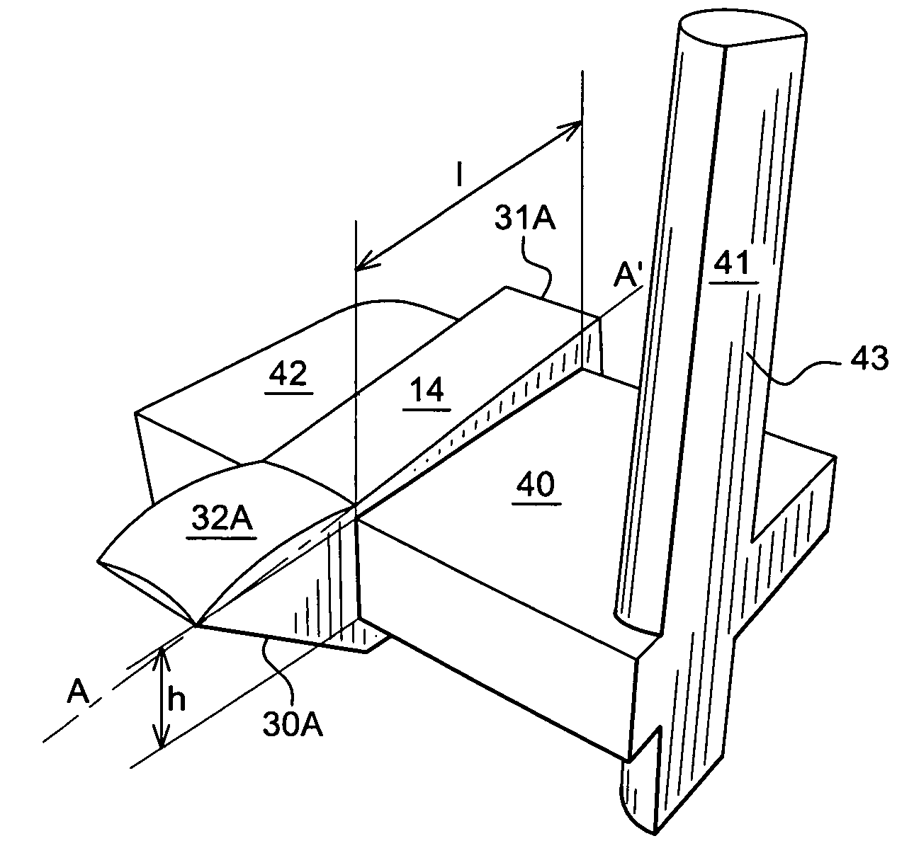
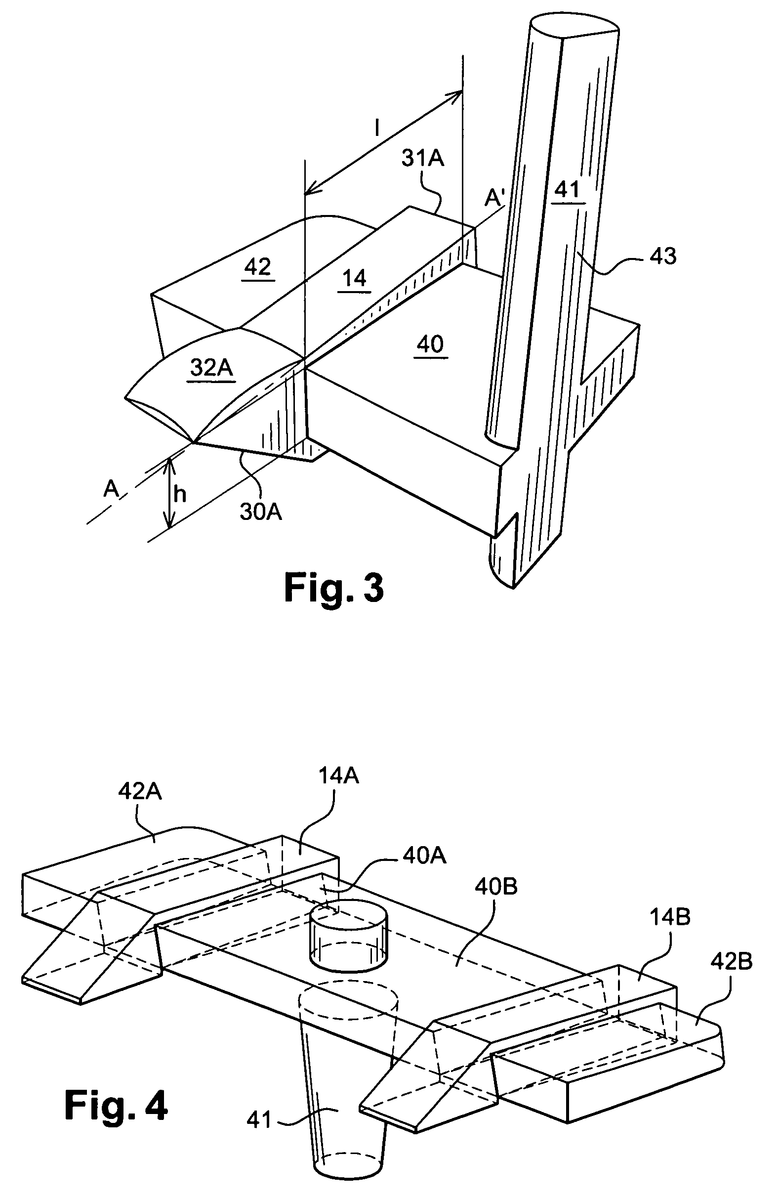
[0029]FIG. 1 shows an embodiment of the light duct and it also shows one way of mounting said duct, in this example on a frame of the pair of spectacles type.

[0030]In the context of the invention, the light duct 14 could be slightly different. In particular, the axis of revolution B-B′ of the lens need not be perpendicular to the first axis A-A′, but could be inclined at an angle lying in the range 75° to 90° relative to said axis. This makes it possible to adapt the ergonomics of the light duct once mounted, so that it fits more closely to the shape of the user's face.

[0031]Furthermore, the duct may also be mounted on a specific system that is placed in front of the eyes of a user, other than a spectacle frame.

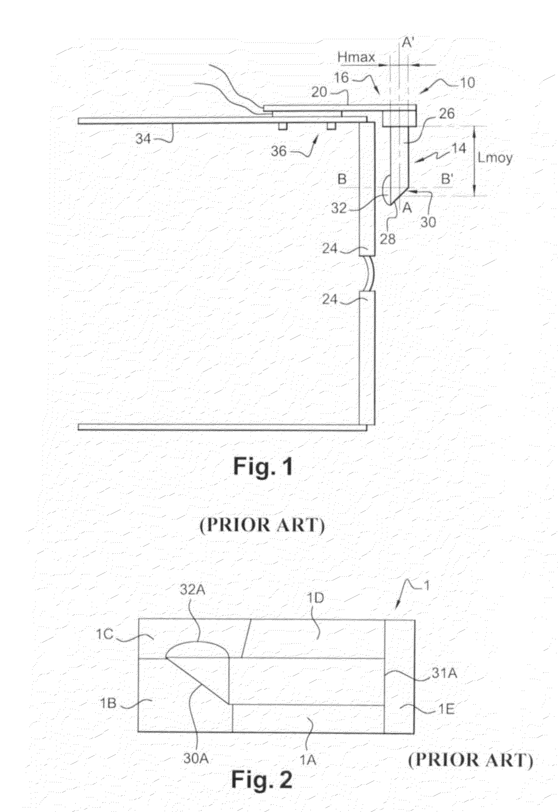
[0032]In the method in accordance with the invention, a mold 1 is used that is made up of a plurality of portions or inserts, as shown in FIG. 2. One insert is used per face of the duct that is to be fabricated.

[0033]More precisely, the mold has five inserts 1A to 1E with the...


PUM

PropertyMeasurementUnit
temperatureaaaaaaaaaa
length Lmoyaaaaaaaaaa

Abstract

A method of fabricating a light duct includes making the light duct as a single piece by injection molding a thermoplastic material in a mold (1) presenting a cavity of shape identical to that of the duct, the injection taking place through a feed orifice disposed on one side of said cavity over a face that is substantially parallel to the plane defined by axes (A-A′, B-B′), the feed orifice presenting a height h lying in the range 0.2 Hmax and Hmax, and a length l lying in the range 0.2 Lmoy and 0.8 Lmoy, the thermoplastic material being injected at a rate lying in the range 400 mm3 / s to 1500 mm3 / s.

Description

RELATED APPLICATIONS[0001]The present application is a national phase application of PCT / FR2004 / 050555, which in turn claims the benefit of priority from French Patent Application No. 03 51 207, filed on Dec. 24, 2003, the entirety of which are incorporated herein by reference.FIELD OF THE INVENTION[0002]The present invention relates to a method of fabricating a light duct of thermoplastic material that is intended in particular for use in making an electronic display arrangement mounted on a frame of the pair of spectacles type.BACKGROUND OF THE INVENTION[0003]Such a display arrangement is described in U.S. Pat. No. 6,023,372 and is shown in plan view in FIG. 1.[0004]Such an arrangement 10 comprises a housing assembly 16 having a first enclosure 20 containing a circuit for receiving data or images and containing an imaging assembly. The light transmitted by the imaging assembly is relayed via an optical device 14 to the eye of the user, e.g. through a spectacle lens24. This light d...

Claims


Application Information

Patent Timeline
Patent Type & Authority Patents(United States)
IPC IPC(8): B29D12/00B29D11/00
CPCB29D11/00663
Inventor BUCHON, CEDRIC
Owner ESSILOR INT CIE GEN DOPTIQUE
Why Eureka
Try Eureka