Centrifugal wheel

a centrifugal and centrifugal technology, applied in the direction of propellers, propulsive elements, water-acting propulsive elements, etc., can solve the problems of difficult manufacturing techniques, difficult to keep reinforcing fibers, and limited us

Inactive Publication Date: 2004-12-02
FLAKT SOLYVENT VENTEC
View PDF6 Cites 17 Cited by
  • Summary
  • Abstract
  • Description
  • Claims
  • Application Information

AI Technical Summary

Problems solved by technology

Although composite materials have been used for making all or part of a centrifugal compressor wheel, such use has remained limited because of the cost of composite materials themselves, and because of the difficulty in making fan wheels out of composite materials.
Unfortunately, it turns out to be very difficult to keep the reinforcing fibers in a desired configuration during the injection operation, thereby making the manufacturing technique complex and difficult, by multiplying the number of precautions that need to be taken.
Furthermore, that can lead to parts being made that are of reduced strength, particularly in the fan blades.
Another factor limiting generalized use of composite materials in compressor wheels lies in the need to have tooling that is specific and therefore expensive.
Finally, although parts made out of composite materials can be very strong, it nevertheless turns out that they possess stiffness that usually remains inferior to the stiffness of parts made out of other materials that are commonly used in this field, and in particular parts made of steel.
This is due in particular to the anisotropy of composite materials.
In the field of fan devices, and for given speed of rotation, this leads to the composite wheels deforming more than similar wheels made of steel.
In particular, it turns out that centrifugal compressor wheels made of composite material can lead to deformation that is large enough to lead to the front plate of the wheel rubbing against the inlet air guide.
That phenomenon is particularly troublesome with wheels of great width (ratio of the inlet width of the blade divided by the diameter of the wheels greater than 0.2, or even for narrower wheels that rotate with high peripheral speed, greater than 150 meters per second (m / s)).

Method used


Image

  • Centrifugal wheel
  • Centrifugal wheel
  • Centrifugal wheel

Examples


Embodiment Construction

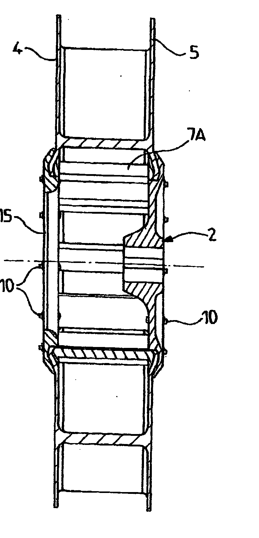
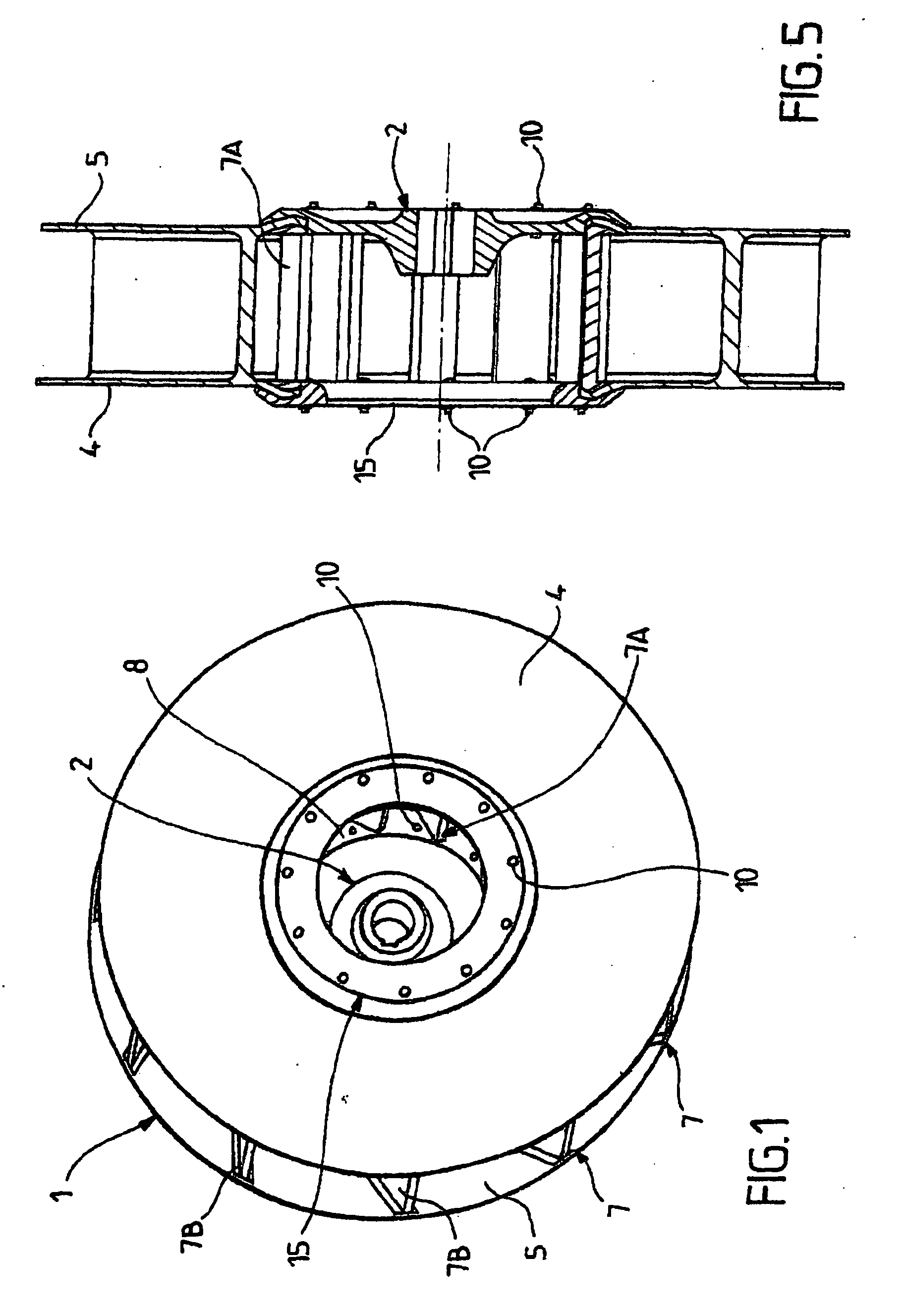
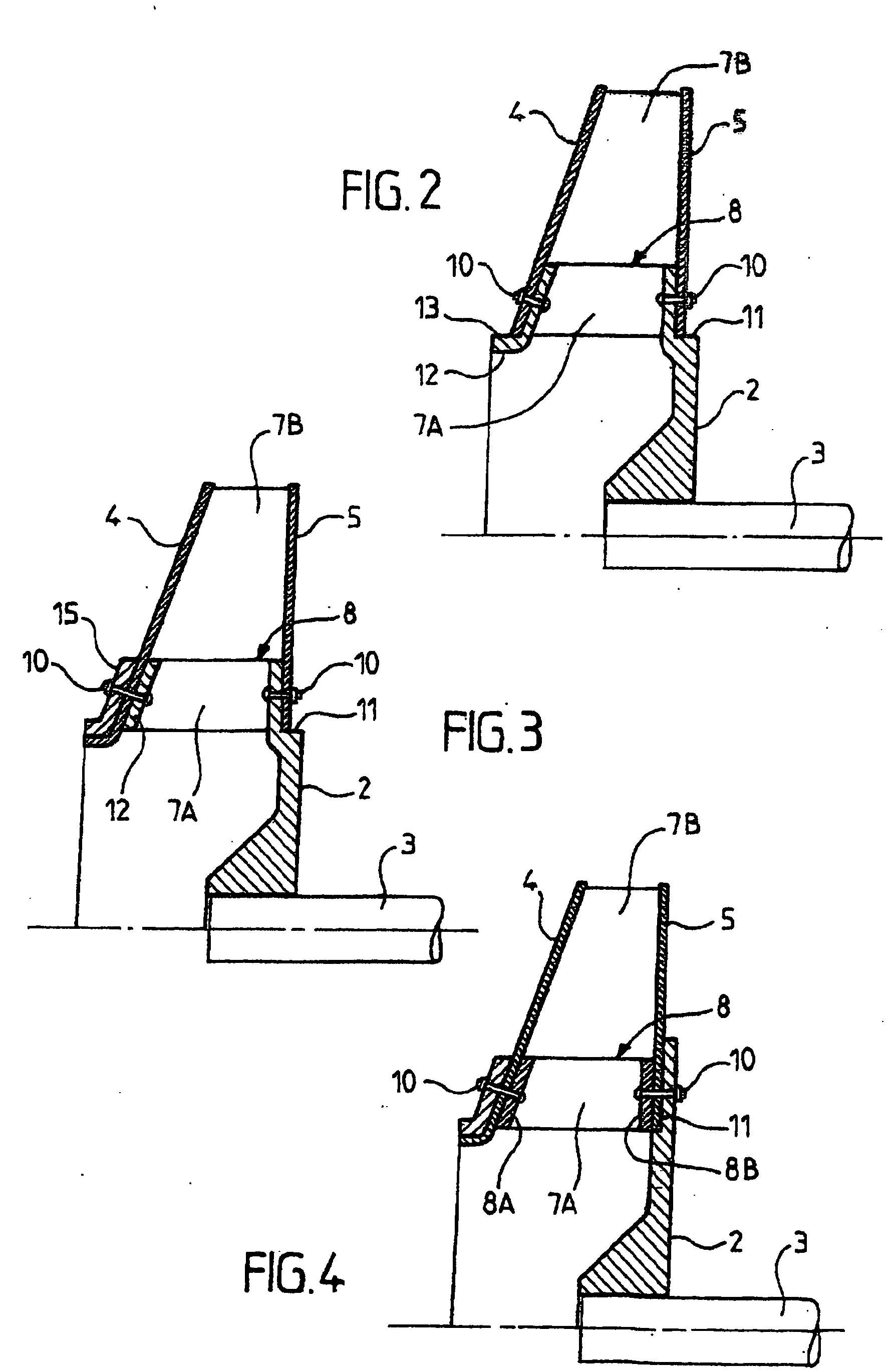
[0024] As shown in FIGS. 1 to 5, the device of the invention comprises a centrifugal compressor wheel 1 itself comprising a metal hub 2 for connection by any known means to a drive shaft 3. The centrifugal compressor wheel 1 is made up of two plates, e.g. circular plates 4 and 5 provided with respective central openings and constituting respectively an inlet plate 4 and an outlet plate 5 for the flow of fluid (generally air) that is to be moved and passed through the fan.

[0025] In conventional manner, a series of blades 7 is interposed between the inlet and outlet plates 4 and 5, thus forming a spacer. The blades 7 are usually disposed in an inclined configuration although they are sometimes purely radial, with this depending on the specific features and the field of application of the centrifugal compressor wheel 1.

[0026] The inlet and outlet plates 4 and 5 may be plane, or they may be conical in shape, or they may be of any other circularly symmetrical shape about the axis of the ...


PUM


Abstract

A centrifugal compressor wheel including a metal hub (2) for connecting to a drive shaft (3), an inlet plate (4) and an outlet plate (5) fixed to the metal hub (2), and a plurality of blades (7), each blade having a beginning and a peripheral portion (7b), fixed between the inner plate (4) and the outer plate (5). The wheel further includes an annular metal insert (8) integrated in the central portion of the wheel at a periphery of the hub (2), the annular metal insert (8) having metal elements (7A) forming the beginnings of the blades of the wheel. The inlet plate (4), the outlet plate (5), and the peripheral portions (7B) of the blades are made of a composite material, thereby constituting a composite portion of the wheel.

Description

[0001] The present invention relates to the technical field of blower wheels or fan wheels or centrifugal compressor wheels for fitting to devices of the fan or centrifugal compressor type.[0002] The present invention relates to a centrifugal compressor wheel comprising a metal hub for connecting to a drive shaft, and having fixed thereon an inlet plate and an outlet plate with fan blades being fixed between them, and the invention also relates to a method of manufacturing it.PRIOR ART[0003] Centrifugal compressor wheels for fitting to a variety of fans or compressors are well known and they generally comprise a series of blades disposed around an axis of rotation and interconnected by circularly symmetrical pieces which may be in the form a disk, a cone, or a ring, or which may be of any toroidal shape.[0004] Proposals have already been made to make all or part of a centrifugal compressor wheel using composite materials, for example of low density, optionally reinforced by short or...

Claims


Application Information

Patent Timeline
Patent Type & Authority Applications(United States)
IPC IPC(8): F04D29/02F04D29/28F04D29/60
CPCF04D29/023F04D29/282F05D2300/10F05D2300/603
Inventor GODICHON, ALAIN FRANCOIS EMILEGUILLEMIN, PIERRE JACQUES FRANCOISGUILLEMIN, SYLVAIN GEORGES RAYMOND
Owner FLAKT SOLYVENT VENTEC
Why Eureka
Try Eureka