[0028] As a solution to the above described problems, the present invention provides a device that has buccal and lingual supports. The supports surround or partially surround a
dental arch buccally and lingually for the purpose of a dental impression. The supports are vertically repeating or vertically extended. The vertically extended or vertically repeating portions of the supports form impression material holding areas. The areas hold
dental impression material. The portions of the supports forming the impression material holding areas help to secure the impression material, allow
free flow of the impression material, and serve as an internal
endoskeleton framework. The device is hygienically, economically and conveniently disposable following a
single use. The present device offers a further solution by providing a device that surrounds or partially surrounds a dental arch and is hollow in the occlusal area and without a separator sheet to section the configuration into upper and lower material containment chambers thereby allowing full surface to surface contact of the teeth and is hygienically, economically and conveniently disposable following a
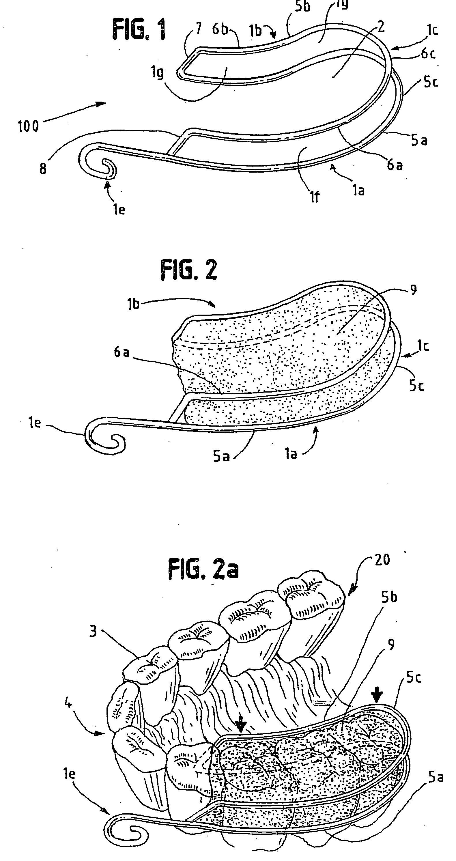
single use. Accordingly, the inventive dental impression device has a buccal support, a lingual support, and a joining section. The buccal support is disposed towards the buccal side of a dental arch; the lingual support is disposed towards the lingual side of a dental arch; and the joining section, which connects the buccal and lingual supports, is disposed posterior in the mouth's no bite region. The supports form impression material holding areas which hold and secure
dental impression material. The supports form an open bite through area through which the lower and
upper teeth's occlusal surfaces can make contact.
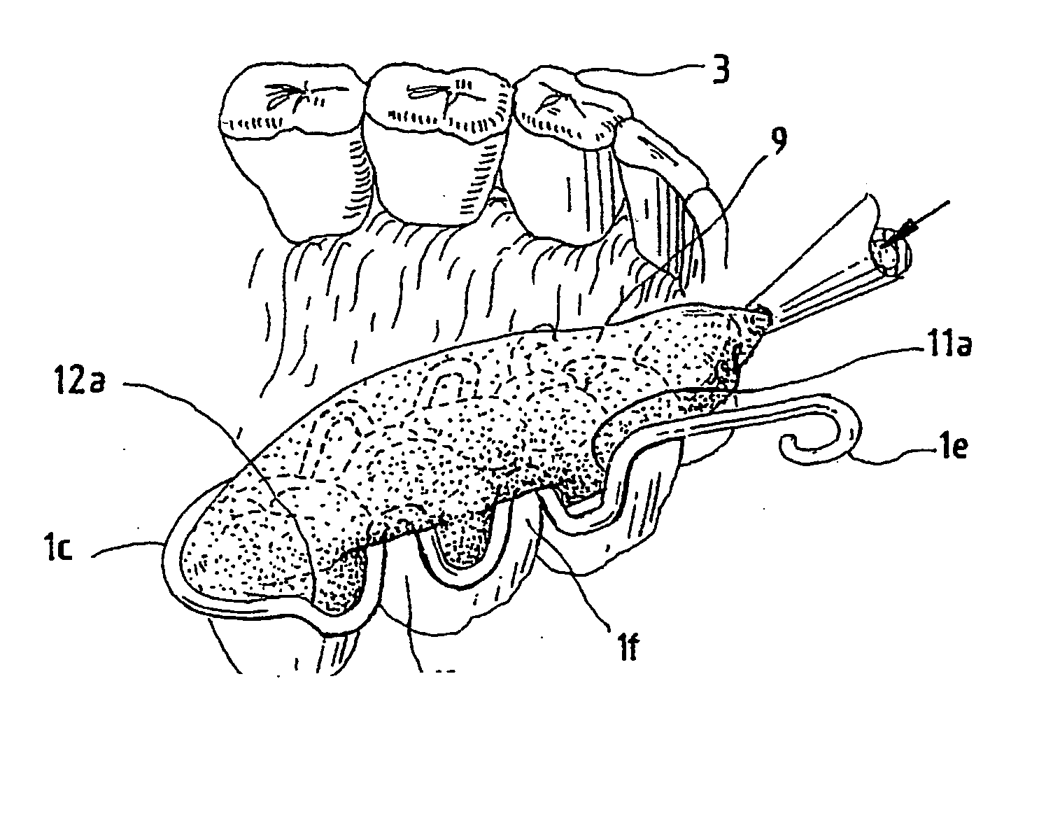
Dental impression material supported in the holding area by the supports is disposed in the open bite area between the occlusal surfaces of the upper and lower teeth. The dental impression is then formed by a person making a closed bite into the impression material. The supports which surround or partially surround the dental arch, may be used to carry impression material to the mouth, hold the impression material in place during the impression process, become predominantly enveloped, surrounded, or buried within the impression material, and provide support and reinforcement, by way of forming an internal framework and
endoskeleton. The device secures the set material for removal from the mouth and throughout the subsequent model preparation procedure. The device is inherently incapable of cross
contamination due to the device being inexpensively fabricated and disposable following a single use. The device can hold dental impression pads through the heating process and carry the softened pads to the mouth for placement between the arches.
[0030] As part of a method to obtain a dental impression, the device is placed into the mouth surrounding a lower dental arch or a portion of a lower dental arch. A paste type dental impression material such as a
silicone, a polyvinyl
siloxane, a polyether, a
polysulfide or any other such material, combination or composition that is basically a paste type consistency and is capable of being extruded and is set by chemical cure, is injected directly around the teeth and into the void area between the buccal and lingual arms of the device. The paste should be extruded, excessively thick onto the occlusal surfaces of the lower teeth. Alternatively, a device already containing
thermoplastic material can be inserted into the patient's mouth. The dental impression material used with the device in this case can be a
thermoplastic pre-form material such as a
polycaprolactone, an
ethylene vinyl acetate, a
wax or any other such material, combination or composition that is basically hard at
room temperature, is softened by heat and is set at body temperature in the mouth. This material can be pre-
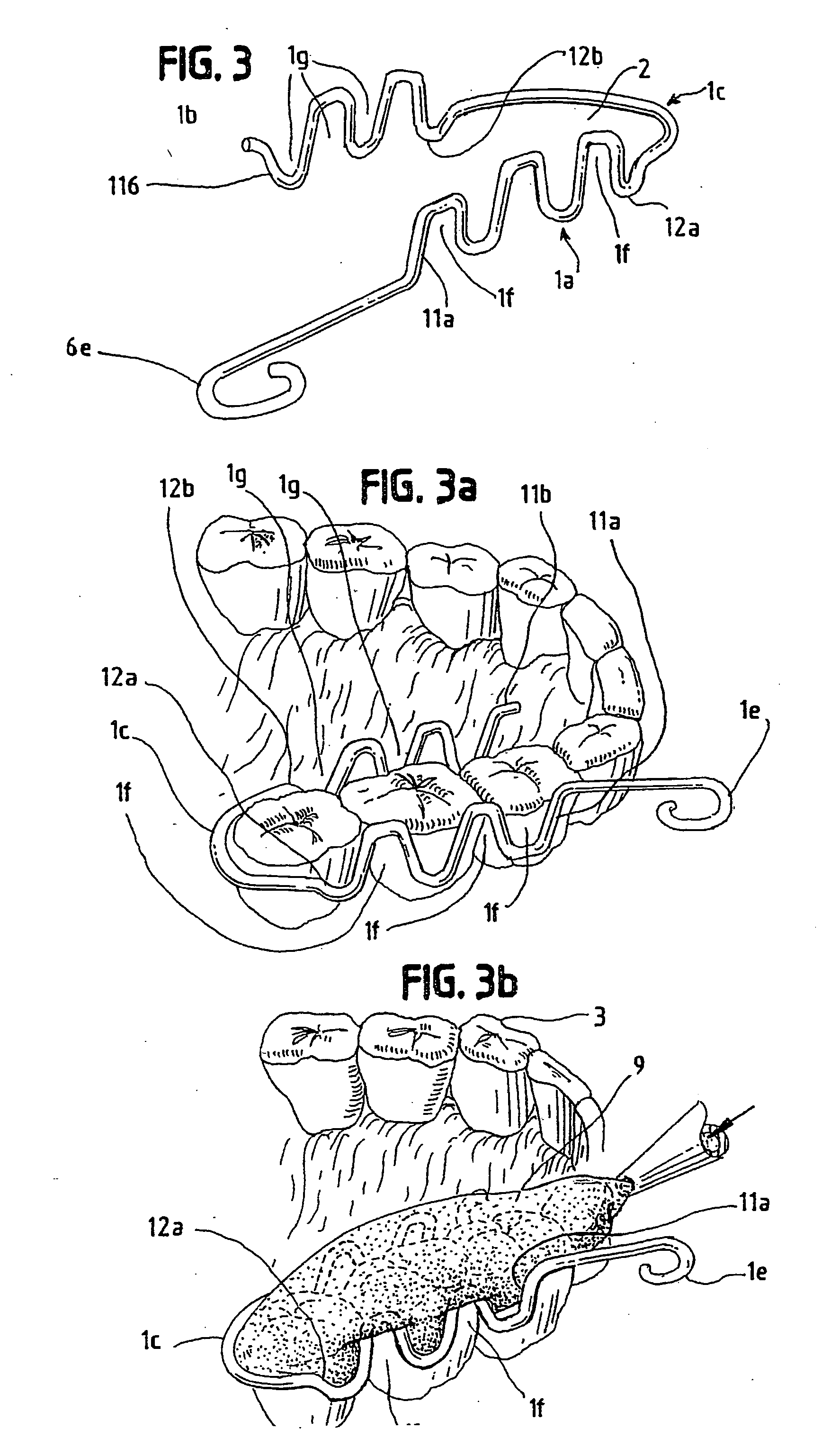
cut or pre-formed into pads or wafers that may be inserted between buccal and lingual arms of the device. It may also be softened and pressed between said arms. When the patient closes into a normal centric
occlusion bite, the soft
thermoplastic impression material extrudes out in all directions freely without constraint. It freely flows through, between and around the supports of the device, enveloping and burying the supports. The full extent of the flow is contained within the
oral cavity and constrained buccally by the mucousal surface of the cheeks and lingually by the tongue. There is no separator sheet between the upper and lower teeth so that full surface-to-surface contact is achieved. There are no sidewalls to flex and relax so that when the material sets, it is in its final and fixed shape. After use and model preparation, the device is discarded. The disposable nature of the device eliminates the need to clean, strip and sterilize. It also totally eliminates the chance of cross
contamination from one patient to the next.

