
Image processing method, apparatus, and program

a technology of image processing and program, applied in the field of image processing methods, apparatuses and programs, can solve the problems of reducing image sharpness, reducing image quality, and unable to obtain satisfactory images, and achieve the effects of reducing image quality, reducing image sharpness, and reducing image sharpness

Inactive Publication Date: 2004-12-16
KONICA MINOLTA INC
View PDF5 Cites 52 Cited by
  • Summary
  • Abstract
  • Description
  • Claims
  • Application Information

AI Technical Summary

Benefits of technology

0034] The number of times of repeating the transform operation in the above-mentioned multi-resolution transform is called a level. As regards the way of naming the level, although there are some differences between persons specialized in the art, in this invention, the way of naming such that a signal of higher resolution is made one of the lower level is employed. That is, in the expression in this invention, the level zero represents an input signal, and the result of the application of a transform operation once to this is named the level 1, and the result of the application of the second transform operation to this result is named the level 2.
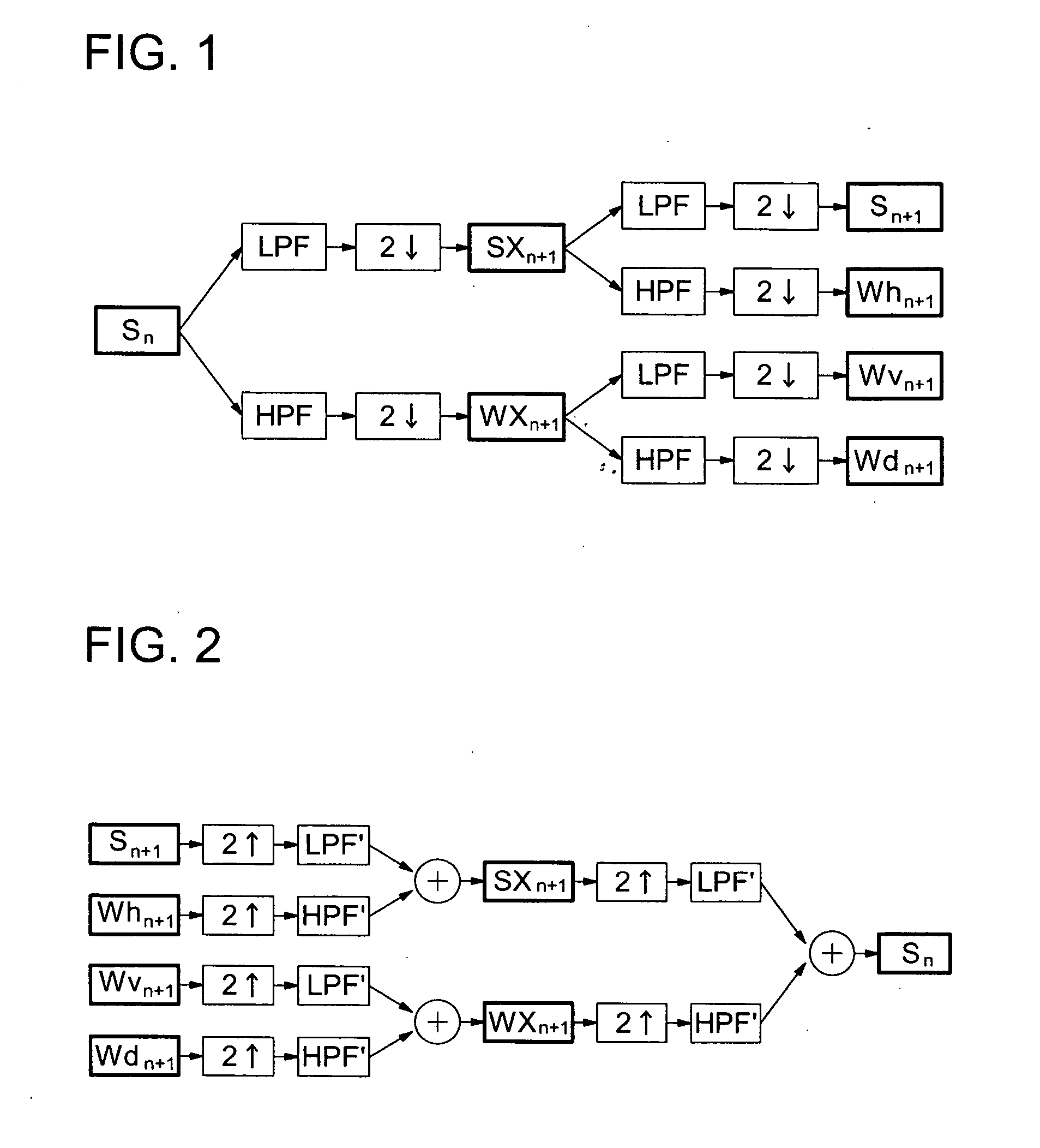
0035] This invention does not limit the method of the multi-resolution transform to a certain one, but it is particularly desirable from the viewpoint of calculation efficiency to use a wavelet transform. The mode of a transform of one level in the case where a wavelet transform is used as a multi-resolution transform will be explained in more detail with reference to FIG. 1.
0036] By applying a one-dimensional low pass filter LPF in the x direction to an input signal S.sub.n, and further, thinning out the result of it by removing one out of every two by a down-sampling means 2, a low-frequency component SX.sub.n+1 which has a half resolution in the x direction to the input signal is obtained. Further, by applying a one-dimensional high pass filter HPF in the x direction to the input signal S.sub.n, and further, thinning out the result of it by removing one out of every two by a down-sampling means 2, a high-frequency component WX.sub.n-1 which has a half resolution in the x direction to the input signal is obtained.
0037] Next, by applying a one-dimensional low pass filter LPF in the y direction to the above-mentioned low-frequency component SX.sub.n+1, and further, thinning out the result of it by removing one out of every two by a down-sampling means 2, a low-frequency component S.sub.n+1 which has a half resolution in the x direction and y direction to the input signal is obtained. In the same way, by applying a one-dimensional high pass filter HPF in the y direction to the low-frequency component S.sub.n+1, and further, thinning out the result of it by removing one out of every two by a down-sampling means 2, a high-frequency component Wh.sub.n+1 which has a half resolution in the x and y directions to the input signal is obtaine

Problems solved by technology

It has been a point of problem that this granular noise signal is remarkably strengthened especially with an image processing of sharpness enhancement, which degrades the quality of the image.
However, because the noise removal based on a simple filter processing which is widely known is accompanied by the lowering of image sharpness, a satisfactory image cannot be obtained.
In a technology disclosed in U.S. Pat. No. 4,812,903 or in a technology disclosed in the publication of the unexamined patent application S63-26783, although some effect can be recognized in the suppression of granular noise being made worse in a sharpness enhancing process, it is not sufficient, and it cannot be expected to suppress a granular noise for a signal before the processing.
If the high-frequency component is remarkably enhanced for compensating this impression of blur, the image becomes unsightly due to the generation of fine noises looking like colors being out of registration in the flat areas such as the cheek.
Further, in any one of the examples of the embodiment described in the publication of the unexamined patent application H9-22460, if it is attempted to enhance the sharpness in fine areas like hairs, the high-frequency component is excessively enhanced, and it is generated a noise looking as if fine powders are scattered over the whole image area.
Further, there is another problem that, in order to separate a low-frequency component from an image signal as intended in the publication of the unexamined patent application H9-22460, it is necessary to apply a processing with a very large-sized low pass filter to every channel of the color signal representing the original image (for example, each of the signal channels of B, G, and R), which makes the load of calculation for the image processing very heavy; this is also a very big problem.
The method proposed in the publication of the unexamined patent application 2000-215307 eases somewhat the above-mentioned defect by dynamically controlling the degree of the suppression of the medium-frequency component and the degree of the enhancement of the high-frequency component in accordance with the situation, but it cannot be said that it is sufficient, and it follows the method which has the point of problem in the image quality as it is.
However, a processing by means of a large-sized low pass filter is required for the production of a blur image, which makes the load of calculation in the image processing heavy.
Further, in the method of abstracting a specified photographic object using a blur image, it is difficult to discriminate, for example, "a blue-colored wall from the blue sky", or "the human skin from a beige-colored wall", and the accuracy of discrimination is highly insufficient.
However, when this technology is applied to a color image, the RGB balance of a photographic object near the edge is broken and a false colored contour is produced, which makes the image very unsightly.
On top of it, by the technology disclosed in the publication of the unexamined patent application H6-274615, it is impossible to reduce granular noises included in an image signal.
The technology disclosed in the unexamined patent application H9-212623 is construed as a noise removal technology to carry out what is called a hard coring processing in which an image signal representing a radiation image undergoes a multi-resolution transform, and out of the high-frequency signal values after transform, those signal values not greater than a threshold is made equally to be zero; however, if said technology is applied to a color image, the RGB balance in the vicinity of the edge of a photographic object is broken to produce a false-color contour, which makes the image very unsightly.
For the above-mentioned reasons, it is impossible to use the technology disclosed in the publication of the unexamined patent application H9-212623 for a color image.
If said technology is applied to a color image, RGB balance is broken in areas where mottled unevenness is dissolved to produce false-colored spots, which makes the image very unsightly.
Further, every time at the transform of one level, it is necessary to repeat a noise abstraction processing and a noise removal processing, which makes the load of calculation very heavy.
Further, in the images for medical use which are supposed in the publication of the unexamined patent application 2000-224421, kinds of photographic object are limited and most of the images are comparatively monotonous; however on the other hand, it is characteristic of a color photographic image that there are present mixedly in the image, areas for which different image qualities are desired respectively such as an area where fine structures densely gather against a flat area, a light area against a dark area, etc., as observed in a personal portrait with a background of a wood.
In an color image like this, it is necessary to change the condition of noise removal on the basis of the grasping of the area structure with a wide view of it; however, in the technology disclosed in the publication of the unexamined patent application 2000-224421, it is necessary to judge the condition of a noise removal processing of the nth-level resolution on the basis of the information of the nth-level resolution concerned; therefore, it is difficult to design an algorithm for determining the noise removal condition.
The technology disclosed in the publication of the unexamined patent application 2001-189866 can be construed as a technology to use, in applying a multi-resolution transform to a signal of an image including a still-standing grid image, a filter having a characteristic not to make the main spatial frequency components of a still-standing grid image substantially pass it in the first-level transform; however, this technology is effective only for the removal of a noise having a periodic uniform frequency response like a still-standing grid image, and it is not effective for the removal of a noise having a distribution in the shape and size with its spatial frequency components not concentrated in a particular band like a granular noise in a color photograph.
This technology is one to make the speed of calculation high by carrying out the image processing and coding processing parallel in preparing an image data file premised on the data compression based on a multi-resolution transform; however, in the field of the color photography, it is necessary to prepare a data file based on a common standard which does not use a multi-resolution transform such as a JPEG file or a TIFF file in response to the request of a user, and the method disclosed in the publication of the unexamined patent application 2001-223899 cannot make the speed of the calculation high.
Further, if the technology of the publication of the unexamined patent application 2001-223899 is applied to a color image, it is produced a serious problem also in image quality that a false-color contour is produced in the vicinity of the edge of a photographic object or that false-color spots are produced in a flat portion.

Method used


Image

  • Image processing method, apparatus, and program
  • Image processing method, apparatus, and program
  • Image processing method, apparatus, and program

Examples


example 2

Cohen, Daubechies, Feauveau 5-3

[0041]

2TABLE 2 for Multi-resolution for Inverse multi-resolution transformation transformation Coefficient of Coefficient of Coefficient of Coefficient of low pass high pass low pass high pass filter filter filter filter -0.176777 0.176777 0.353553 0.353553 0.353553 0.353553 1.06066 -0.707107 0.707107 -1.06066 0.353553 0.353553 0.353553 0.353553 -0.176777 0.176777

example 3

Spline 4-12

[0042]

3TABLE 3 for Multi-resolution for Inverse multi-resolution transformation transformation Coefficient of Coefficient of Coefficient of Coefficient of low pass high pass low pass high pass filter filter filter filter -0.013811 0.013811 0.041432 0.041432 0.052481 -0.052481 -0.267927 -0.267927 -0.071816 0.176777 0.176777 0.071816 0.966748 -0.53033 0.53033 0.966748 0.966748 0.53033 0.53033 -0.966748 -0.071816 -0.176777 0.176777 -0.071816 -0.267927 0.267927 0.052481 0.052481 0.041432 -0.041432 -0.013811 -0.013811

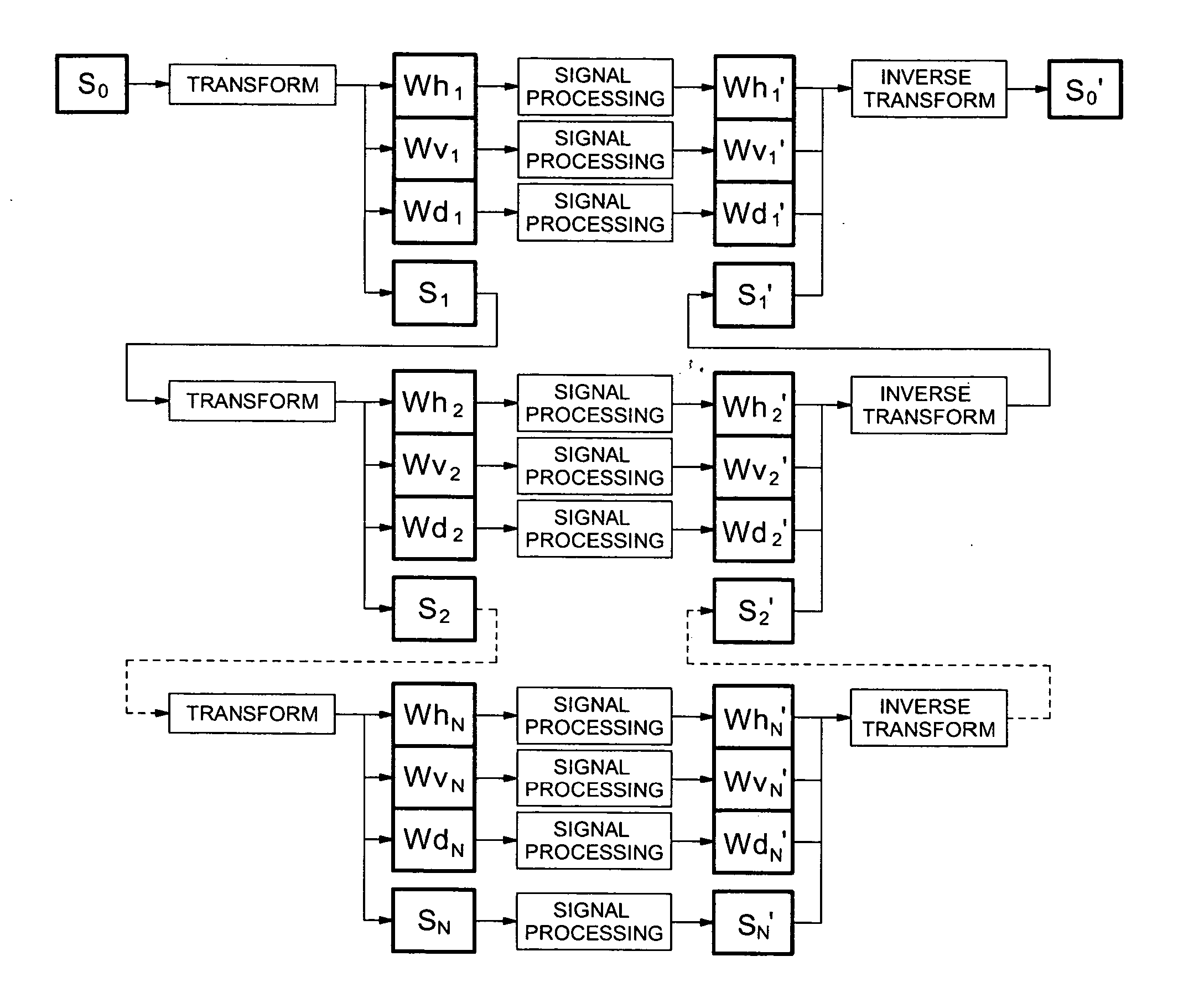
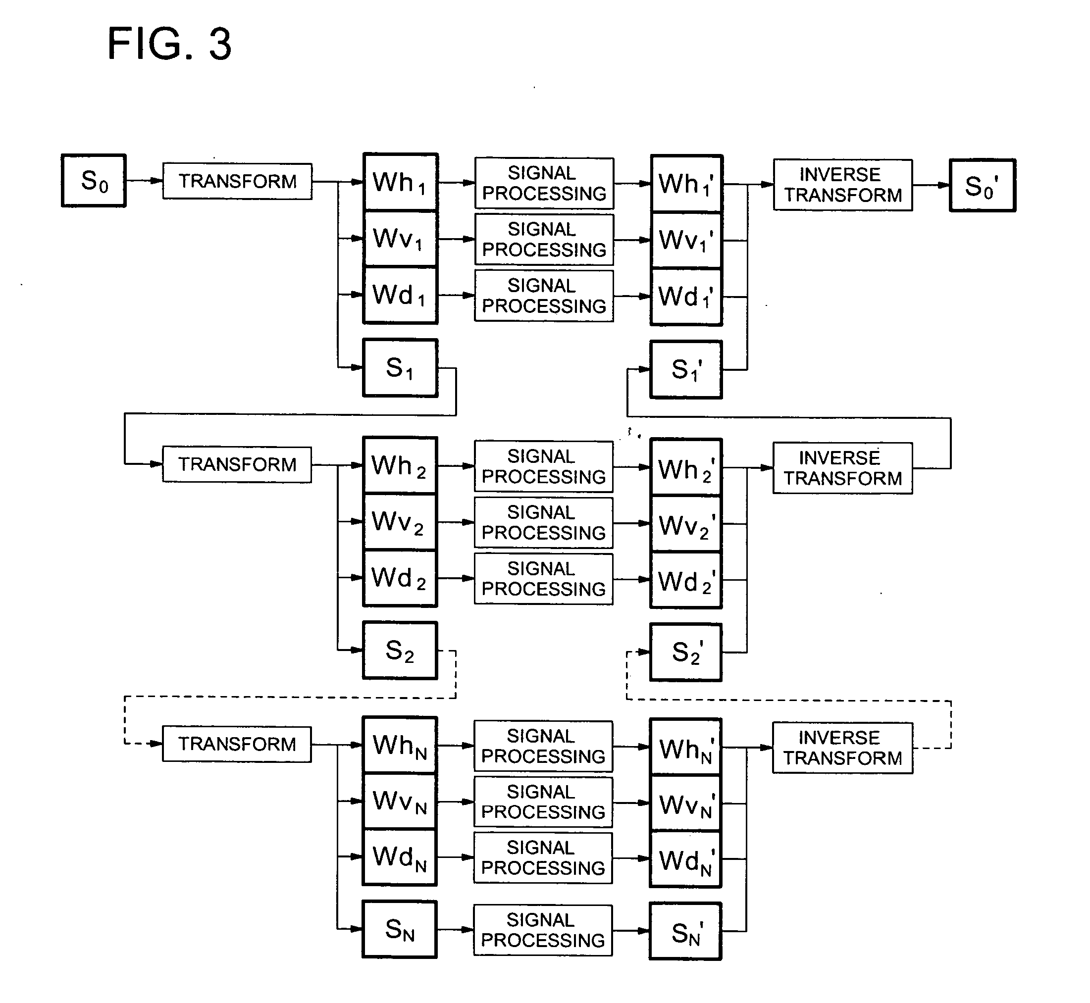
[0043] FIG. 3 is a drawing showing the concept of a multi-resolution transform and an inverse multi-resolution transform in multiple levels. An input signal S.sub.0 is decomposed into high-frequency components of N levels and a low-frequency component of the level N by transform operations of N times. After an image processing to be described later is applied to every component produced, by the inverse transform operations of N times to every component, a processe...


PUM


Abstract

An image processing method, having the steps of: transforming color image signals representing an original image into a luminance signal and color difference signals; transforming the luminance signal and the color difference signals separately into multi-resolution signals of the level 1 to the level N; applying an inverse multi-resolution transform to the color difference multi-resolution signals, after suppressing the high-frequency components of the level 1 of the color difference multi-resolution signals; applying an inverse multi-resolution transform processing to the luminance multi-resolution signals, after applying a coring processing using a condition for each level different from other levels to the high-frequency signals of each level of the luminance multi-resolution signals; transforming the processed luminance signal and the processed color difference signals into a set of processed color image signals.

Description

[0001] This invention relates to a processing method and processing apparatus of a color image, and in particular, to a processing method which can be applied to an image processing method and an image processing apparatus to be applied to an image which has been made a set of image signals by the scanning of a color photograph.[0002] It is put into practice that an image formed on a color photographic film is photoelectrically read by a CCD sensor or the like, to be converted into a set of image signals. This set of image signals, after being undergone various kinds of image processing represented by negative-to-positive reversing, luminance adjustment, color balance adjustment, granular noise removal, and sharpness enhancement, are distributed through a medium such as a CD-R, a floppy disk, or a memory card, or an Internet line, and outputted as a hard copy image by a silver halide photographic paper, an ink jet printer, a thermal printer, or the like, or displayed on a medium suc...

Claims


Application Information

Patent Timeline
IPC IPC(8): G06T1/00G06T5/20H04N1/409H04N1/46H04N1/58H04N1/60
CPCH04N1/58
Inventor ITO, TSUKASA
Owner KONICA MINOLTA INC
Features
  • Generate Ideas
  • Intellectual Property
  • Life Sciences
  • Materials
  • Tech Scout
  • Unparalleled Data Quality
  • Higher Quality Content
  • 60% Fewer Hallucinations
Learn More