
Techniques for secure free space laser communications

Inactive Publication Date: 2004-12-23
THE JOHN HOPKINS UNIV SCHOOL OF MEDICINE
View PDF23 Cites 74 Cited by
  • Summary
  • Abstract
  • Description
  • Claims
  • Application Information

AI Technical Summary

Problems solved by technology

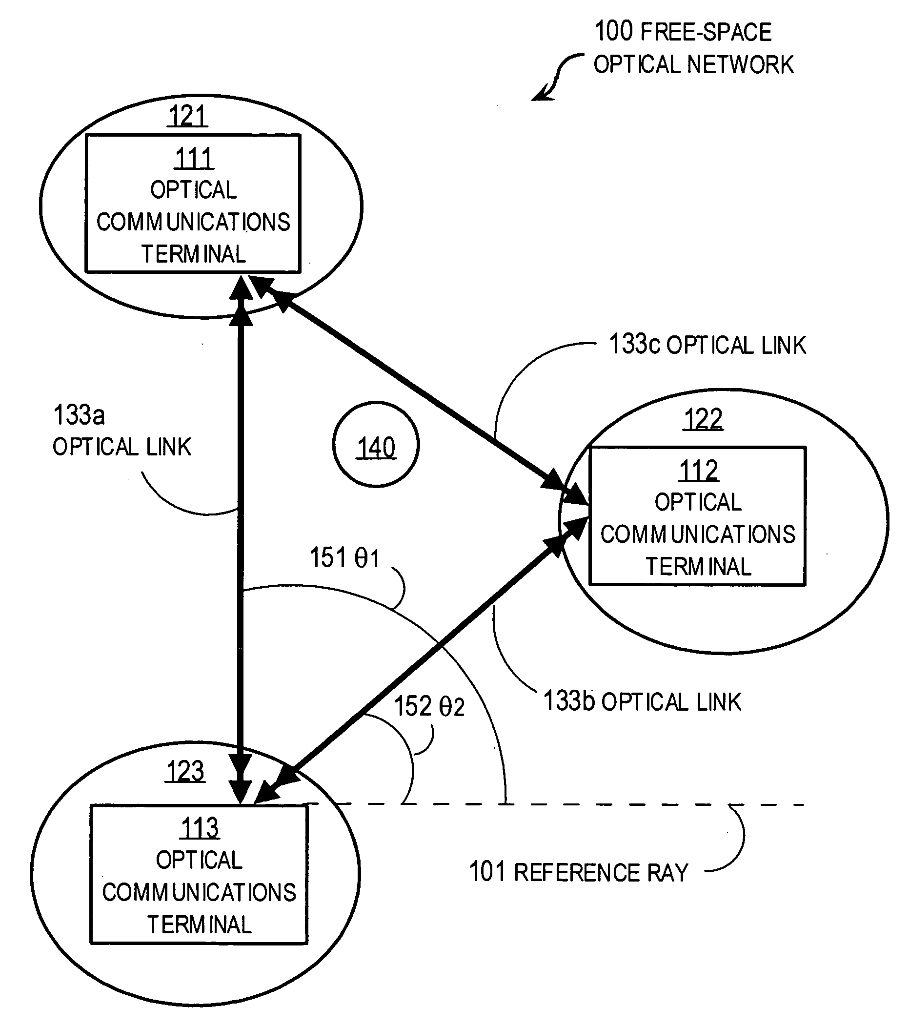
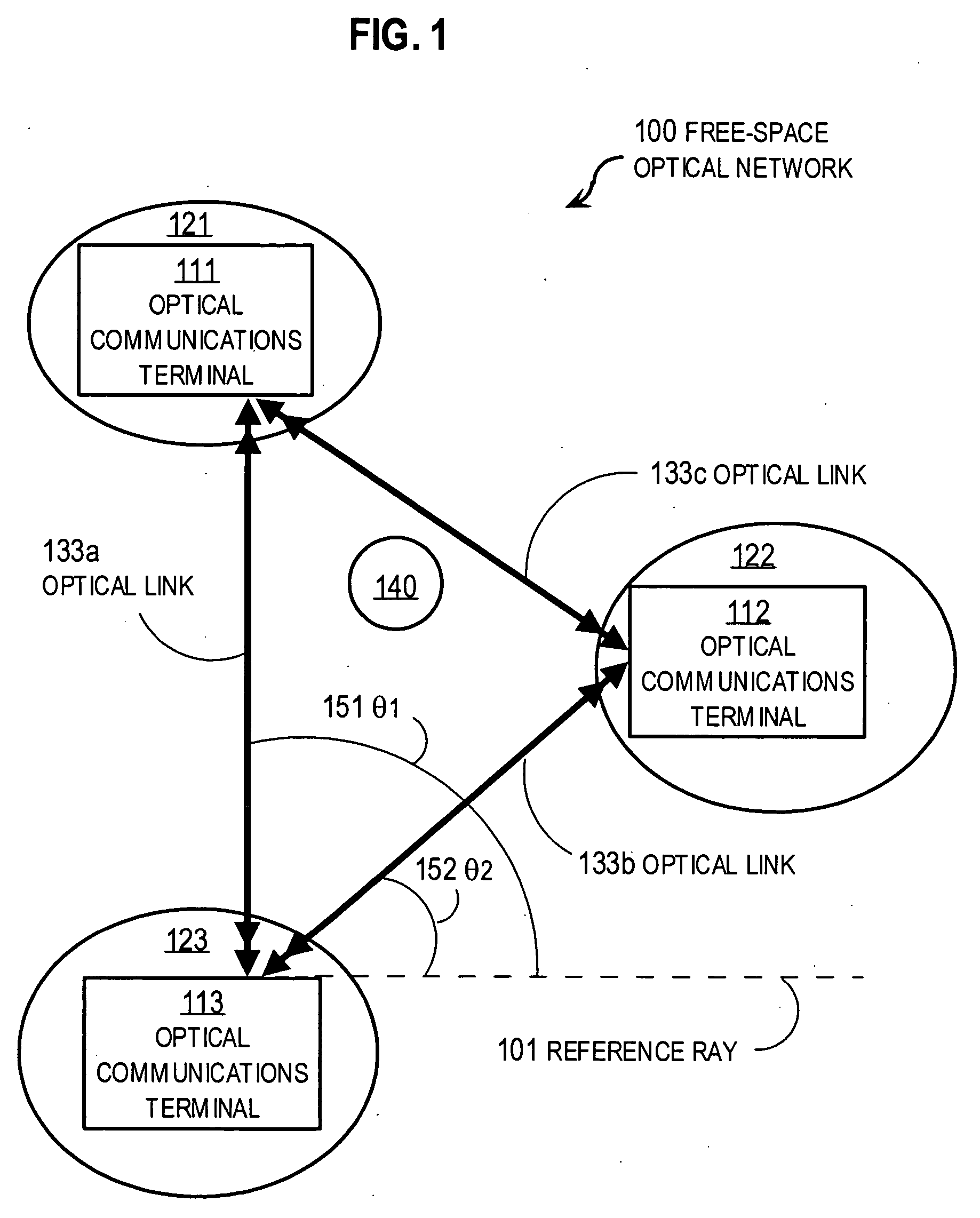
Among the challenges in establishing networks of optical free-space communications links is pointing accuracy.
The free space paths are quite long in some scenarios, e.g., from ground or aircraft to satellite, so small pointing errors can cause a beam to entirely miss an intended terminal.
The problem is especially difficult with aircraft moving in different directions with large accelerations.
Another challenge is security.
Because the optical links are in free-space, they are subject to interference and interception by entities that are not under the control of the parties trying to communicate over the link.
Network integrity and the network's quality of service (QOS) contracts may be compromised by non-malicious interference, such as caused by aircraft and atmospheric phenomena, or by malicious interference by mischievous or hostile entities.
Hostile entities may try to intercept optical signals transmitted over the links to extract the information thereon, jam the links by sending high energy signals that swamp legitimate signals, spoof communications by sending data that appears valid but is actually misleading or damaging, or perform other attacks.
Authentication alone, however, does not prevent jamming and interception attacks.
In some embodiments, Krill uses optical switches instead of micromechanical mirrors because of perceived drawbacks in the time it takes from issuing an electrical command to the end of the mechanical adjustment commanded.
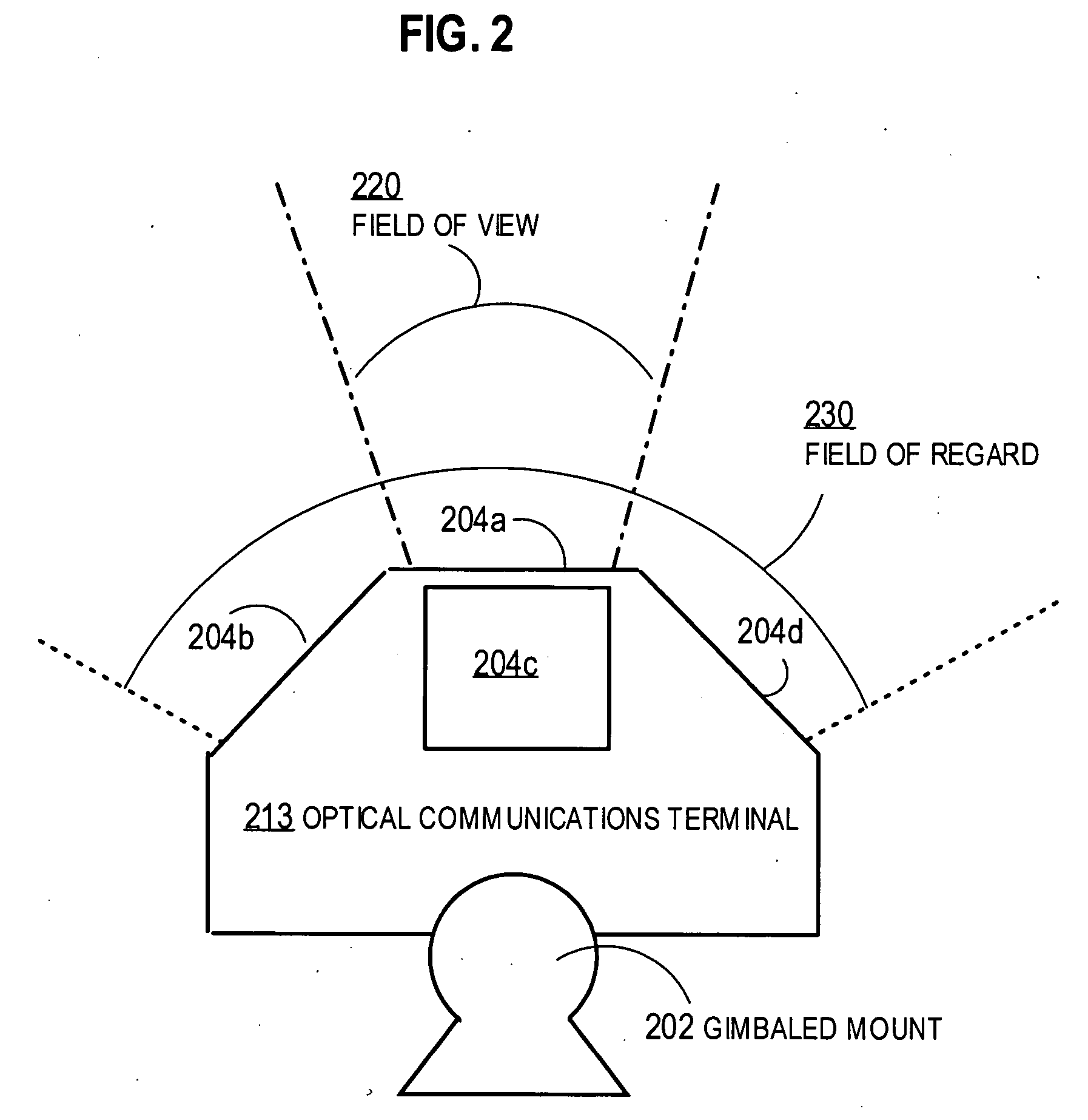
The risk of an undesirable effect which imposes a performance or security problem is also determined to occur within the wide field of view.
The processors also determine that there is a risk of an undesirable effect which imposes a security or performance cost within the wide field of view.
In some embodiments, undesirable object is a hostile vehicle intent on intercepting secure communications, or jamming the signals on legitimate optical links with one or more spurious optical signals.
Such signal processing may consume considerable computational resources at the local terminal and only imperfectly retrieve the signal from the desired source 321.
For example, if a signal from the jamming source 340 is especially effective, it may be impossible for signal processing to separate the signal from the desired source in sufficiently short time to maintain communication, if at all.
In some situations, the narrow field of view might include the jamming source only and consume resources trying to process a signal that does not include any legitimate signals.
In some embodiments, during step 420, the processor determines a risk that an undesirable effect is in the field of view.
Pointing the narrow field of view on a known position of the desired terminal decreases the risk of including one or more undesired terminals in the wide field of view, even when the positions of the undesired terminals are not known or are known to be widely scattered.

Method used


Image

  • Techniques for secure free space laser communications
  • Techniques for secure free space laser communications
  • Techniques for secure free space laser communications

Examples


Embodiment Construction

[0069] FIG. 5B is a block diagram that illustrates an apparatus 501 for independently steering multiple optical links with micro-mechanical mirrors, according to a more detailed embodiment. Apparatus 501 may be used in a terminal for free-space optical communications and includes a multi-channel transceiver board 510 for optical communication, a multi-channel steering board 530 for steering free-space optical beams, and telescopic optics 550. As in FIG. 5A, electrical connections are indicated by thin lines without arrowheads, optical paths are indicated by thick lines with arrowheads indicating the direction or directions of propagation. Free-space optical paths are indicated by double arrowheads, while optical paths in optical waveguides are indicated by single arrowheads. In the illustrated embodiment, four optical communications channels arranged along one dimension are illustrated; and each channel makes use of several optical components that are individually well known in the ...


PUM


Abstract

Techniques for establishing a free-space optical communications link between a local terminal and a remote terminal include determining that a remote terminal is within a wide field of view associated with a micromechanical mirror in a local terminal. The risk of an undesirable effect which imposes a performance or security problem is also determined to occur within the wide field of view. The micromechanical mirror is pointed by including the remote terminal within a narrow field of view that is narrower than the wide field of view, and by reducing the risk that the undesirable effect is within the narrow field of view.

Description

[0001] This application claims benefit of U.S. Provisional Application. 60 / 479,274, filed Jun. 18, 2003, the entire contents of which are hereby incorporated by reference as if fully set forth herein, under 35 U.S.C. .sctn.119(e).[0002] 1. Field of the Invention[0003] The present invention relates to free-space optical communications; and, in particular, to techniques for aiming laser beams to improve security in free-space laser communications.[0004] 2. Description of the Related Art[0005] Free-space laser communications systems have been proposed for mobile communications in sparsely populated areas and in military applications, among others. For example, see United States Patent Application Publication US2004 / 0001720, by J. A. Krill, D. D. Duncan, C. R. Moore, J. Cipriano, and R. M. Sova, entitled "Satellite-based mobile communication system" (hereinafter Krill), the entire contents of which are hereby incorporated by reference as if fully set forth herein.[0006] Free-space laser...

Claims


Application Information

Patent Timeline
IPC IPC(8): G03H1/00H04B10/10
CPCH04B10/1125
Inventor BOONE, BRADLEY G.DUNCAN, DONALD D.SOVA, RAYMOND M.
Owner THE JOHN HOPKINS UNIV SCHOOL OF MEDICINE
Learn More