Arc tube and low-pressure mercury lamp that can be reduced in size

a mercury lamp and arc tube technology, applied in the direction of low-pressure discharge lamps, discharge tubes luminescnet screens, gas-filled discharge tubes, etc., can solve the problems of thermal electrons not reaching the desired temperature when energized, loss of life or a lighting failure of the lamp, and difficulty in moving thermal electrons inside the arc tube smoothly

Inactive Publication Date: 2004-12-30
PANASONIC CORP
View PDF10 Cites 15 Cited by
  • Summary
  • Abstract
  • Description
  • Claims
  • Application Information

AI Technical Summary

Benefits of technology

[0015] According to this construction, a length of the multiple-coiled filament along a coil axis direction can be reduced without causing a coil touch that tends to occur in a conventional arc tube in which a multiple-coiled filament is wound a plurality of turns in a last coiling stage.

Problems solved by technology

However, such downsizing of arc tubes causes the following problems.
When a coil touch occurs, the filament coil fails to reach a desired temperature when energized.
This causes an electron emissive material on the filament coil to remain without being decomposed, which results in a loss of life or a lighting failure of the lamp.
This makes it difficult for thermal electrons to move smoothly inside the arc tube.

Method used


Image

  • Arc tube and low-pressure mercury lamp that can be reduced in size
  • Arc tube and low-pressure mercury lamp that can be reduced in size
  • Arc tube and low-pressure mercury lamp that can be reduced in size

Examples


second embodiment

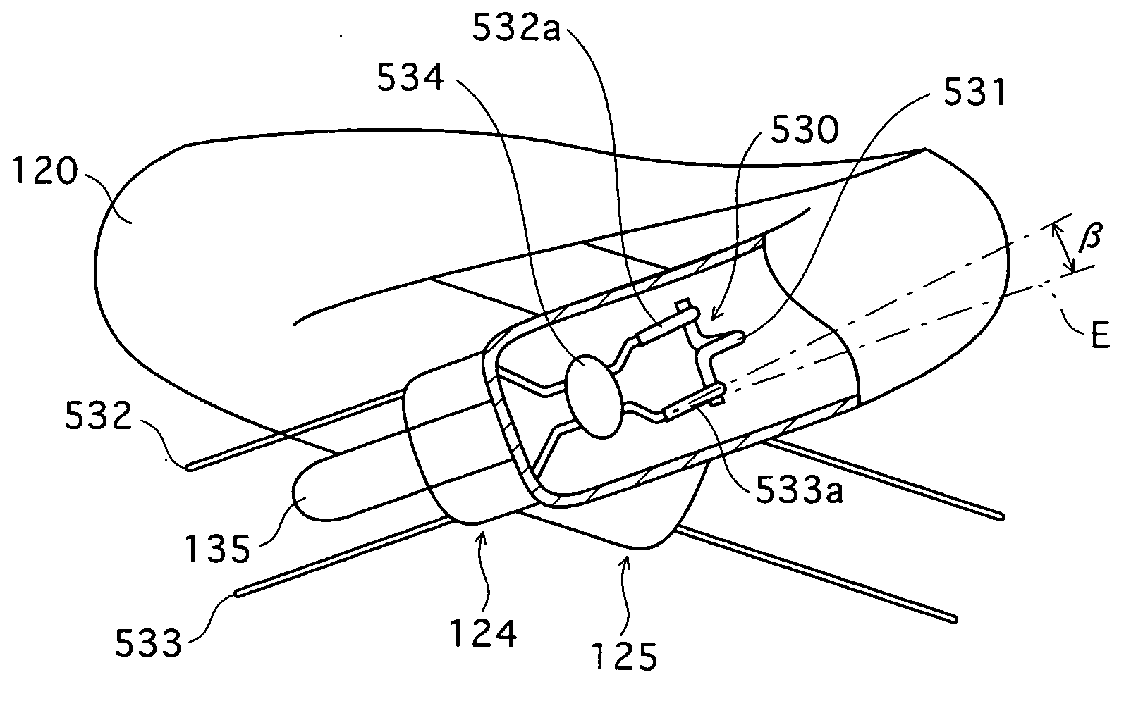
[0113] FIGS. 4A and 4B show a state where an electrode 530 which is the first example of the second embodiment is sealed at each of the ends 124 and 125 of the arc tube body 115. In these drawings, part of the end 124 is cut away to illustrate the electrode 530 in detail.

[0114] When the electrode 530 is viewed from the direction orthogonal to the pinch plane (which is parallel to the paper surface of FIG. 4A), portions 532a and 533a of a pair of lead wires 532 and 533 on a filament coil side of a bead 534 are angled (inclined) along the end 124 of the arc tube body 115, as shown in FIG. 4A.

[0115] In more detail, the portions 532a and 533a of the lead wires 532 and 533 are angled by angle .beta. toward the connecting unit 121 of the arc tube body 115, with respect to a direction (indicated by line segment E) that is parallel to a central axis of the electrode 530 (corresponding to central axis C shown in FIG. 3).

[0116] Angle .beta. is determined by angle .alpha. at which the end 124 ...

first embodiment

[0117] Such an electrode 530 can be obtained from the electrode 130 of the first embodiment in the following manner. While holding the bead 134 of the electrode 130, the portions of the lead wires 132 and 133 on the filament coil side of the bead 134 are bent at their bases by angle .beta. with respect to the direction parallel to central axis C of the electrode 130.

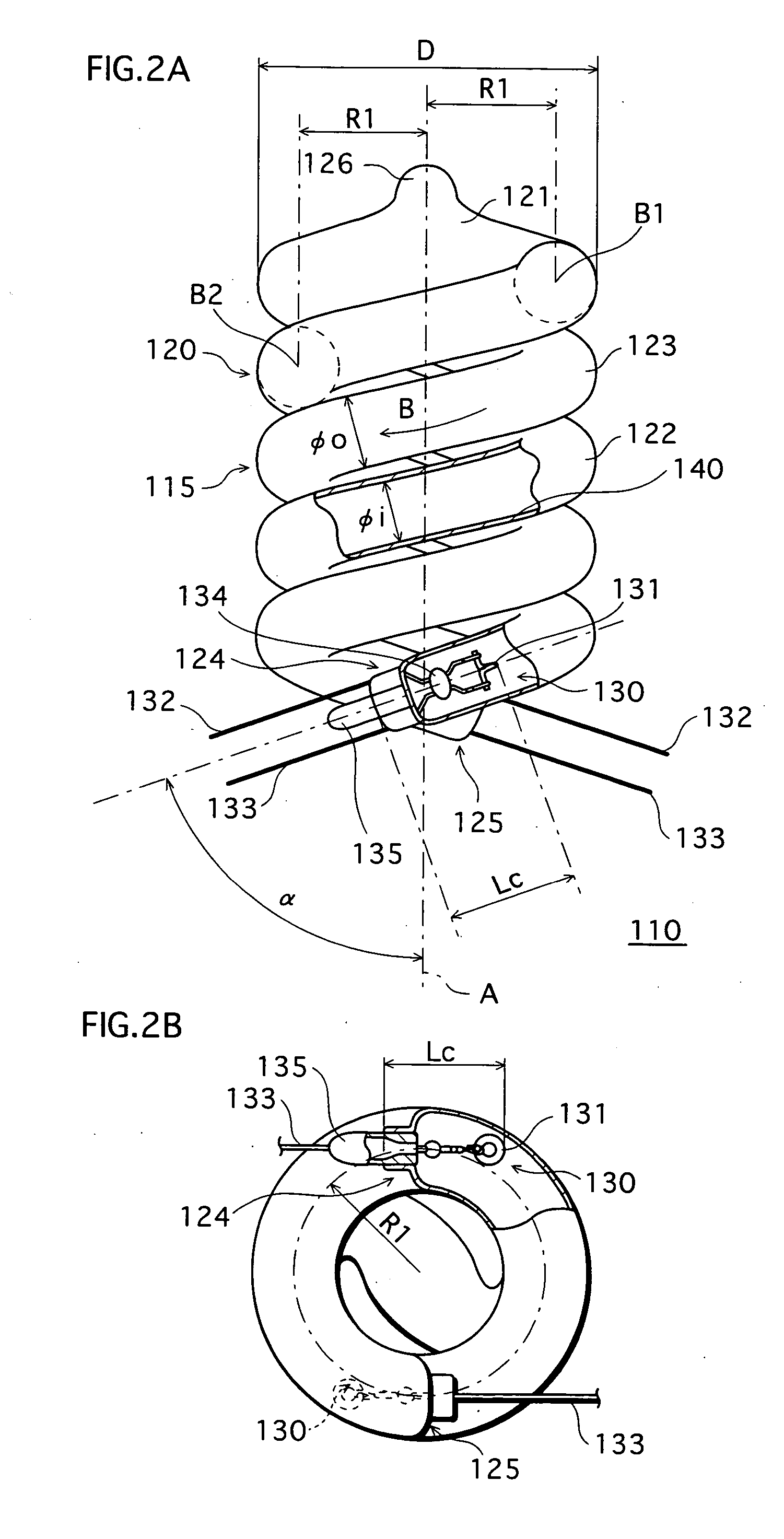
[0118] Also, when the electrode 530 is viewed from the spiral axis direction, portions of the lead wires 532 and 533 to be positioned within the arc tube body 115 are curved along the end 124 of the arc tube body 115, as shown in FIG. 4B.

[0119] In more detail, the portions of the lead wires 532 and 533 to be positioned within the arc tube body 115 are curved along the tubular axis of the glass tube 120 which turns around spiral axis A with turning radius R1. To curve the lead wires 532 and 533 in this way, for example, the lead wires 532 and 533 are deformed along a circumferential surface of a die having a desired curva...

second example

(b) SECOND EXAMPLE

[0120] FIGS. 5A and 5B respectively show states where electrodes 630 and 730 which are the second example of the second embodiment are sealed at each of the ends 124 and 125 of the arc tube body 115, when viewed from the spiral axis direction. Here, part of the end 124 is cut away to illustrate the electrodes 630 and 730 in detail.

[0121] In FIG. 5A, a pair of lead wires 632 and 633 of the electrode 630 are angled at at least one point (633a) in the discharge space of the arc tube 110, at angle .gamma.1 with respect to the pinch plane (which is orthogonal to the paper surface of FIG. 5A). In FIG. 5B, a pair of lead wires 732 and 733 of the electrode 730 are angled at at least one point (733a) in the discharge space of the arc tube 110, at angle .gamma.2 with respect to the pinch plane.

[0122] In more detail, if a distance between a discharge space side of the sealed part of the arc tube 110 and the angled point of the lead wires is less than half of distance Dc betwe...


PUM


Abstract

An arc tube includes an arc tube body and a pair of electrodes. The arc tube body is formed from a glass tube which is double-spirally wound from a middle portion to both ends around a spiral axis. The pair of electrodes are sealed at both ends of the arc tube body. Mercury is enclosed in the arc tube substantially in a single form. Each of the electrodes includes a multiple-coiled filament which is wound substantially one turn in a last coiling stage.

Description

[0001] This application is based on an application No. 2003-155490 filed in Japan, the contents of which are hereby incorporated by reference.[0002] 1. Field of the Invention[0003] The present invention relates to an arc tube in which electrodes including filament coils are sealed at ends of an arc tube body, and a low-pressure mercury lamp including the arc tube.[0004] 2. Related Art[0005] With the advent of the energy-saving era, research is being performed into low-pressure mercury lamps such as fluorescent lamps. In particular, increasing attention has been given to compact self-ballasted fluorescent lamps as alternative light sources to incandescent lamps. As an example, a compact self-ballasted fluorescent lamp includes a 3U-type arc tube in which three glass tubes bent in the shape of U are connected to form an arc tube body (e.g. Japanese Patent Application Publication H09-231825).[0006] One long discharge space is formed in this 3U-type arc tube. Electrodes are sealed at bo...

Claims


Application Information

Patent Timeline
Patent Type & Authority Applications(United States)
IPC IPC(8): H01J61/067H01J61/00H01J61/04H01J61/30H01J61/32H01J61/72
CPCH01J61/0672H01J61/327
Inventor NAKANISHI, AKIKOIWASE, KOHHEINAKANO, KENJIITAYA, KENJITANI, SEIDOUUCHIDA, NORIYUKI
Owner PANASONIC CORP
Why Eureka
Try Eureka