Wearable finger montion sensor for sensing finger motion and method of sensing finger motion using the same
a finger and sensor technology, applied in the direction of mechanical pattern conversion, instruments, cathode-ray tube indicators, etc., can solve the problems of inconvenience in attaching and removing the sensor from the finger, long use time, and inability to achieve size reduction and low power consumption
- Summary
- Abstract
- Description
- Claims
- Application Information
AI Technical Summary
Benefits of technology
Problems solved by technology
Method used
Image
Examples
first embodiment
[0044] The same numerals and symbols used in the first embodiment will be used for identical elements in the second exemplary embodiment.
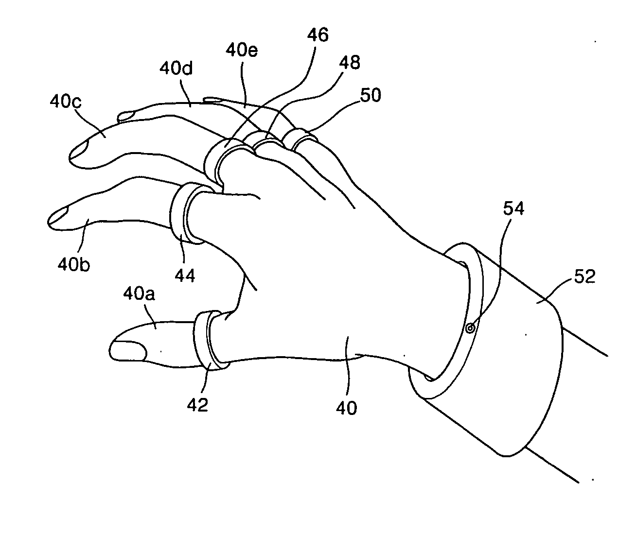
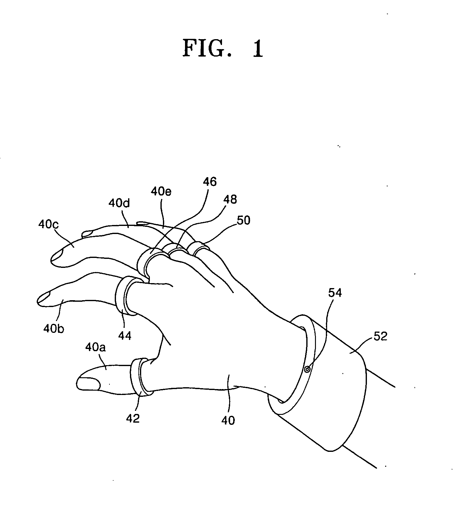
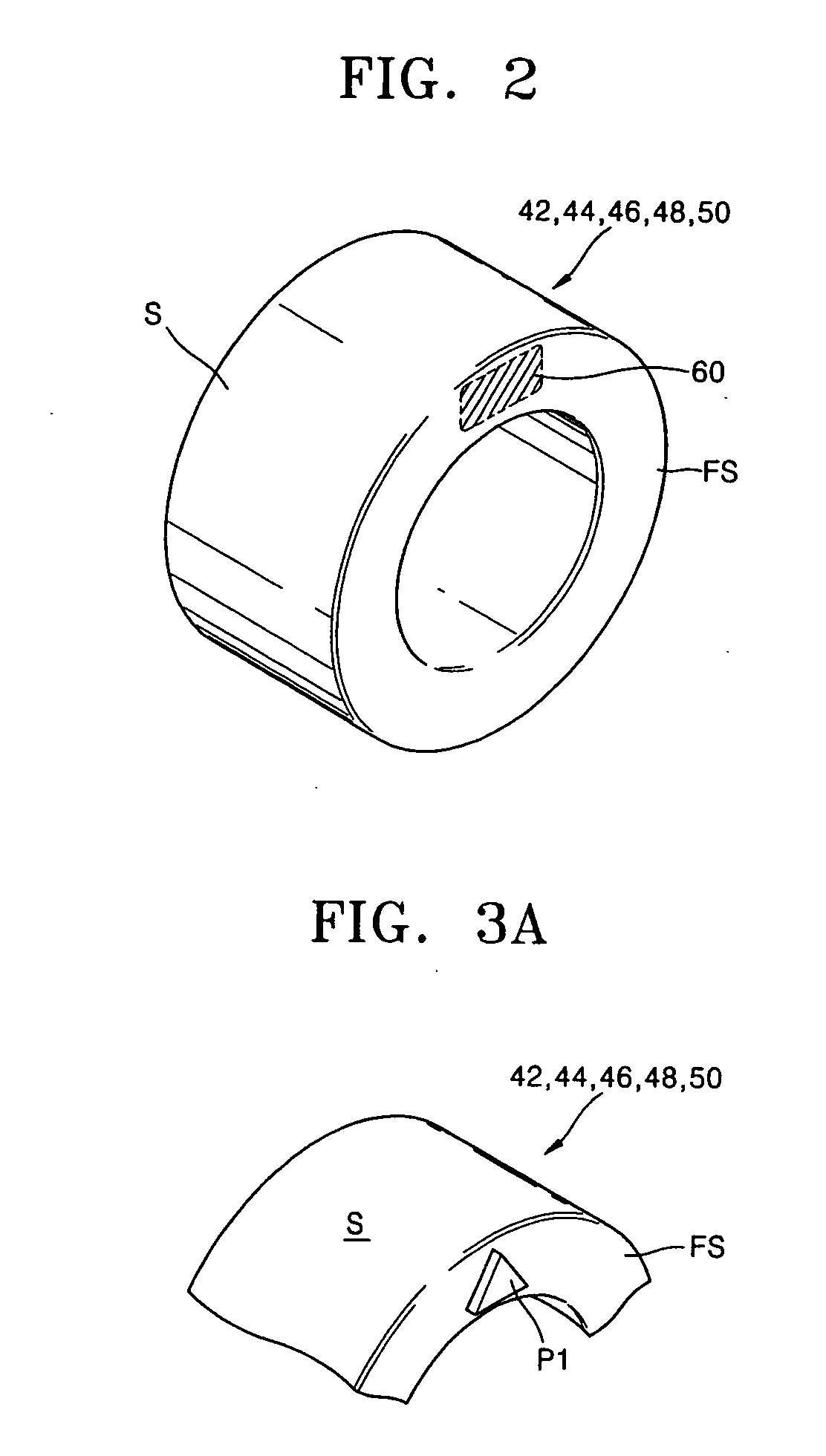
[0045] Referring to FIG. 5, a wearable finger motion sensor according to the second exemplary embodiment of the present invention comprises sixth through tenth rings 70, 72, 74, 76, and 78 to be worn on the thumb 40a, index finger 40b, middle finger 40c, ring finger 40d, and little finger 40e, respectively, and a second bracelet 80 to be worn on the wrist. A visual sensor 54 and first and second infrared emission devices 82 and 84 are disposed on a face of the second bracelet 80 so as to face toward the sixth through tenth rings 70, 72, 74, 76, and 78. Preferably, the first and second infrared emission devices 82 and 84 are light emitting diodes (LED). Discharged infrared light from the first and second infrared emission devices 82 and 84 are input to the visual sensor 54 after reflecting off of the sixth through tenth rings 70, 72, 74, 76, and 78....
second embodiment
[0053] FIGS. 8 through 11 are photographed images of fingers taken by the visual sensor 54 equipped on a wearable finger motion sensor according to the first and second embodiment of the present invention. The images are taken while demonstrating motions of the index finger, middle finger, and ring finger of the right hand wearing the wearable finger motion sensor. Bright spots in the picture are the infrared reflection mirrors.
[0054] As shown in FIG. 8, the three rings worn on the index finger, middle finger, and ring finger are all showing. In this case, the image signal processing section does not transmit any signal to the wireless communication module because the sensor recognizes that there is no motion of the fingers. Accordingly, no data is transmitted from the bracelet to the peripheral devices.
[0055] However, as shown in FIG. 9, the ring on the index finger is not visible in the image or the infrared light is not reflected from the ring on the index finger, and the image p...
PUM
 Abstract
Description
Claims
Application Information
 - R&D
- Intellectual Property
- Life Sciences
- Materials
- Tech Scout
- Unparalleled Data Quality
- Higher Quality Content
- 60% Fewer Hallucinations
Browse by: Latest US Patents, China's latest patents, Technical Efficacy Thesaurus, Application Domain, Technology Topic, Popular Technical Reports.
© 2025 PatSnap. All rights reserved.Legal|Privacy policy|Modern Slavery Act Transparency Statement|Sitemap|About US| Contact US: help@patsnap.com


