Display device with rail support

a technology of display module and support, which is applied in the direction of display means, advertising, identification means, etc., can solve the problems of high failure rate of conventional signs, high shipping costs, and high repair process, and achieve the effect of reducing the stress on the display module(s)

Inactive Publication Date: 2005-01-06
LUMINATOR HLDG
View PDF27 Cites 23 Cited by
  • Summary
  • Abstract
  • Description
  • Claims
  • Application Information

AI Technical Summary

Benefits of technology

[0014] To remedy the deficiencies of conventional display signs used in mass transit vehicles, the principles of the present invention provides for modular display modules to be mounted to an elongate mounting system in a limited manner to result in minimal stresses to be applied to the display modules, thereby reducing failure rates of the signs and simplifying repair efforts. The elongate mounting system includes at least one mounting surface of a elongate mount and is operable to receive the display modules. The mounting system also includes at least one fastener for securing a single edge of the at least one display module to the elongate mount and at least one mounting bracket that secures the elongate mount to the mass transit vehicle.
[0016] One embodiment of a display sign according to the principles of the present invention includes a elongate mount operable to be mounted on a mass transit vehicle and at least one display module configured to be coupled to the elongate mount and operable to display alphanumeric characters of a variety of fonts including Roman characters, Arabic script, etc. The display module(s) may secured to the elongate mount along a single edge to reduce stresses to the display module(s).

Problems solved by technology

Because mass transit vehicles are prone to vibration inducing or dynamic environments, failure rates of the conventional signs is high.
Due to the cumbersome size and weight of the frame assemblies 100, shipping costs are high and at least two people are needed to maneuver and install the sign.
If any portion of the sign, including the LED boards 16 and frame assembly 100, malfunctions, the repair process is very tedious and time-consuming even though the malfunction itself may be trivial.
In addition, the frame assemblies 100 typically installed in mass transit vehicles may not adequately withstand many of the stresses associated with a moving vehicle.

Method used


Image

  • Display device with rail support
  • Display device with rail support
  • Display device with rail support

Examples


Embodiment Construction

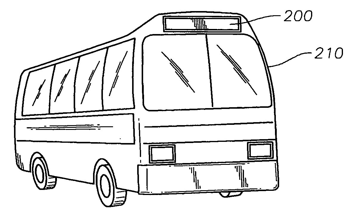
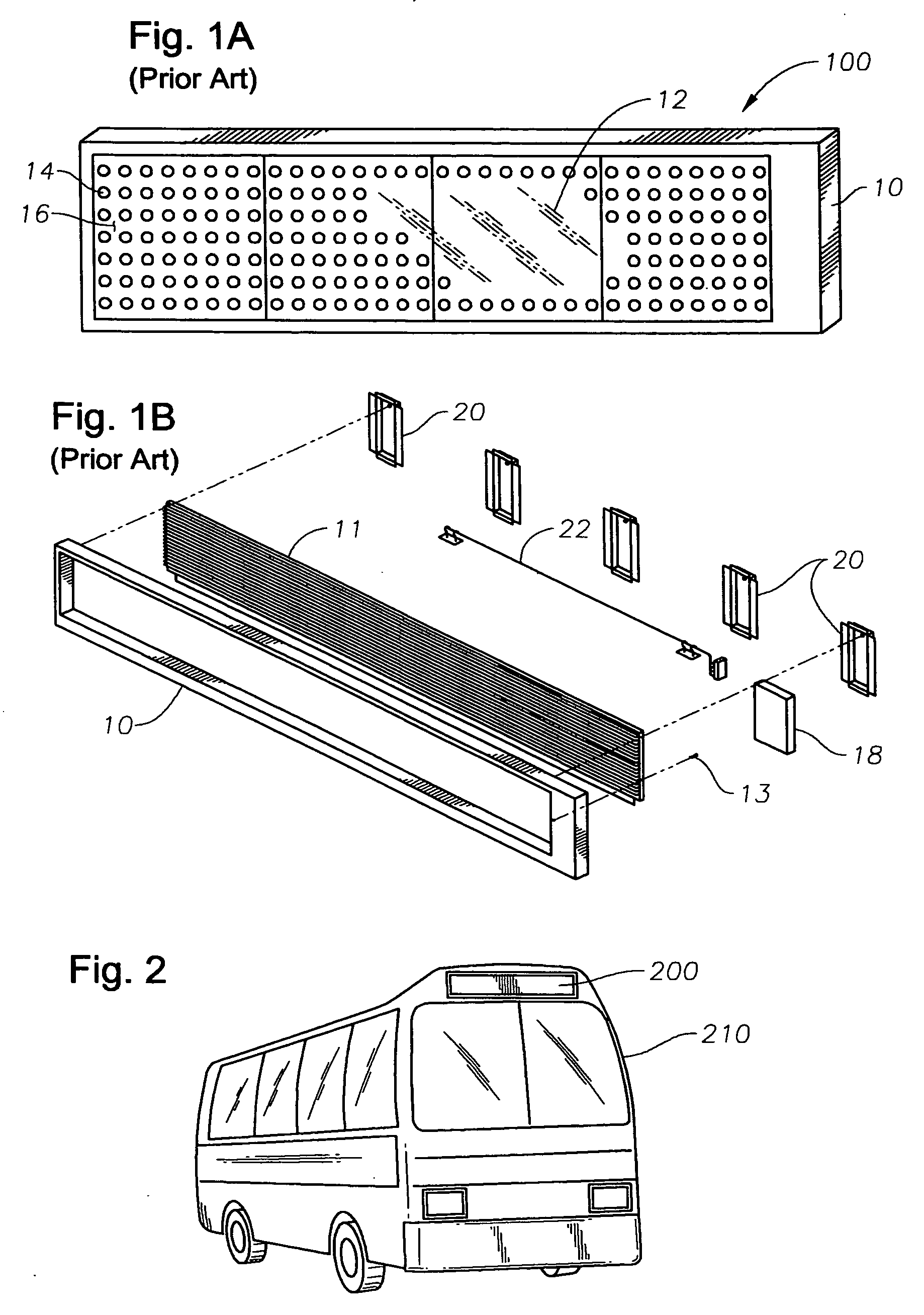
[0042] The principles of the present invention provide for an electronic signs system for vehicles to be composed of self-contained display modules and an elongate mount adapted to support the display modules and mount to the vehicle so as to minimize potential damage to the display modules. The vehicles can include mass transit vehicles or other types of vehicles. Some examples of mass transit vehicles includes buses, trains, or other vehicles that display information and / or advertisements to passengers or the public. The display modules may include electronic display elements, electronics, and a housing. In one embodiment, the housing is composed of a louver structure and a backplate optionally operable as a heat sink. In lieu of the louver structure, the housing can incorporate another structure that allows the electronic display elements to be visible. Some examples of alternates can include a transparent material optionally treated to reduce glare or an apertured structure thro...


PUM


Abstract

Disclosed is a display device, elongate mount, and display module for displaying alphanumeric information to passengers of a mass transit vehicle. The display modules are mounted along a single edge to a elongate mount. The elongate mount includes at least one end cap which is made of a vibration dampening material. The louver of the display device includes a substantially continuous pressure member in order to place substantially continuous elongate contact to an area of an LED board that houses at least one heating element. The at least one heating element is covered by a thermally conductive foam that transmits heat from the elements to a heat sink of the display module.

Description

BACKGROUND OF THE INVENTION [0001] 1. Field of the Invention [0002] The present invention relates to display devices and more particularly, to programmable displays for use on vehicles and about stations. [0003] 2. Description of the Related Art [0004] Existing mass transit vehicles, such as buses and trains, carry destination and other signs for the purpose of conveying information to passengers using the mass transit vehicles. Destination signs inform passengers outside of the vehicle of the route information (route number and description). These signs may transmit information through a variety of display mechanisms. A sign may use light emitting diodes (LEDs), flip dot technology, or liquid crystal displays (LCDs), for example, in order to present alphanumeric information to the passengers. The destination signs normally are placed at the front of a mass transit vehicle over the windshield. The signs are mounted to the existing vehicle structure with various mounting brackets. [0...

Claims


Application Information

Patent Timeline
Patent Type & Authority Applications(United States)
IPC IPC(8): G09F9/33G09F21/04
CPCG09F21/04G09F9/33
Inventor GRAY, JAMES EARLGUNTER, JOHN BARTHOLOMEW
Owner LUMINATOR HLDG
Why Eureka
Try Eureka