Steam Turbine Rotating Blade

a steam turbine and rotating blade technology, which is applied in the direction of liquid fuel engines, vessel construction, marine propulsion, etc., can solve the problems of exacerbated difficulty in designing steam turbine blades, blades are also subject to vibration, etc., and achieve optimized flow distribution, minimal centrifugal and bending stresses, and optimized aerodynamic performance

a steam turbine and rotating blade technology, which is applied in the direction of liquid fuel engines, vessel construction, marine propulsion, etc., can solve the problems of exacerbated difficulty in designing steam turbine blades, blades are also subject to vibration, etc., and achieve optimized flow distribution, minimal centrifugal and bending stresses, and optimized aerodynamic performance

US20100021306A1Active Publication Date: 2010-01-28NUOVO PIGNONE TECH SRL

Image

  • Steam Turbine Rotating Blade
  • Steam Turbine Rotating Blade
  • Steam Turbine Rotating Blade

Examples


Embodiment Construction

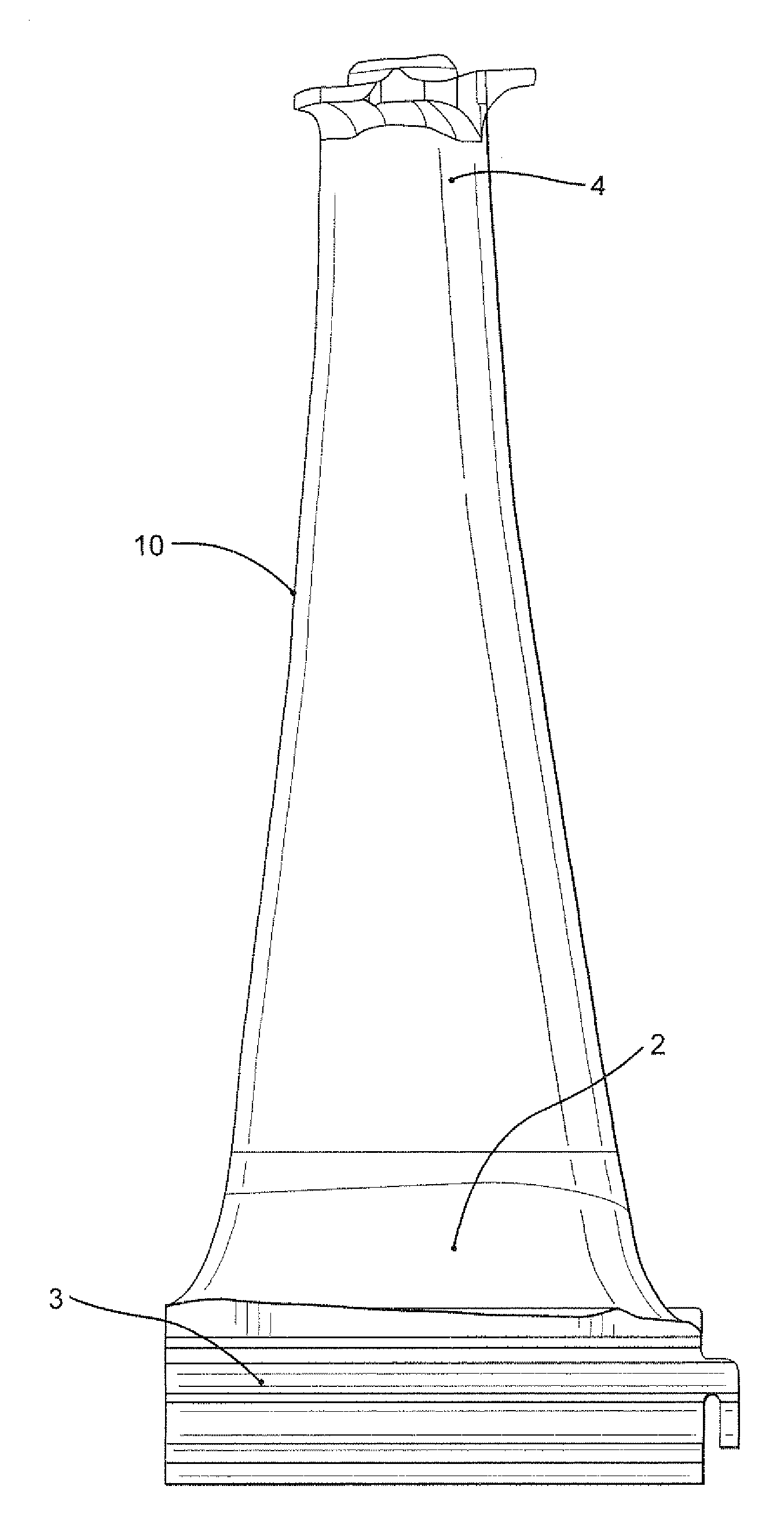
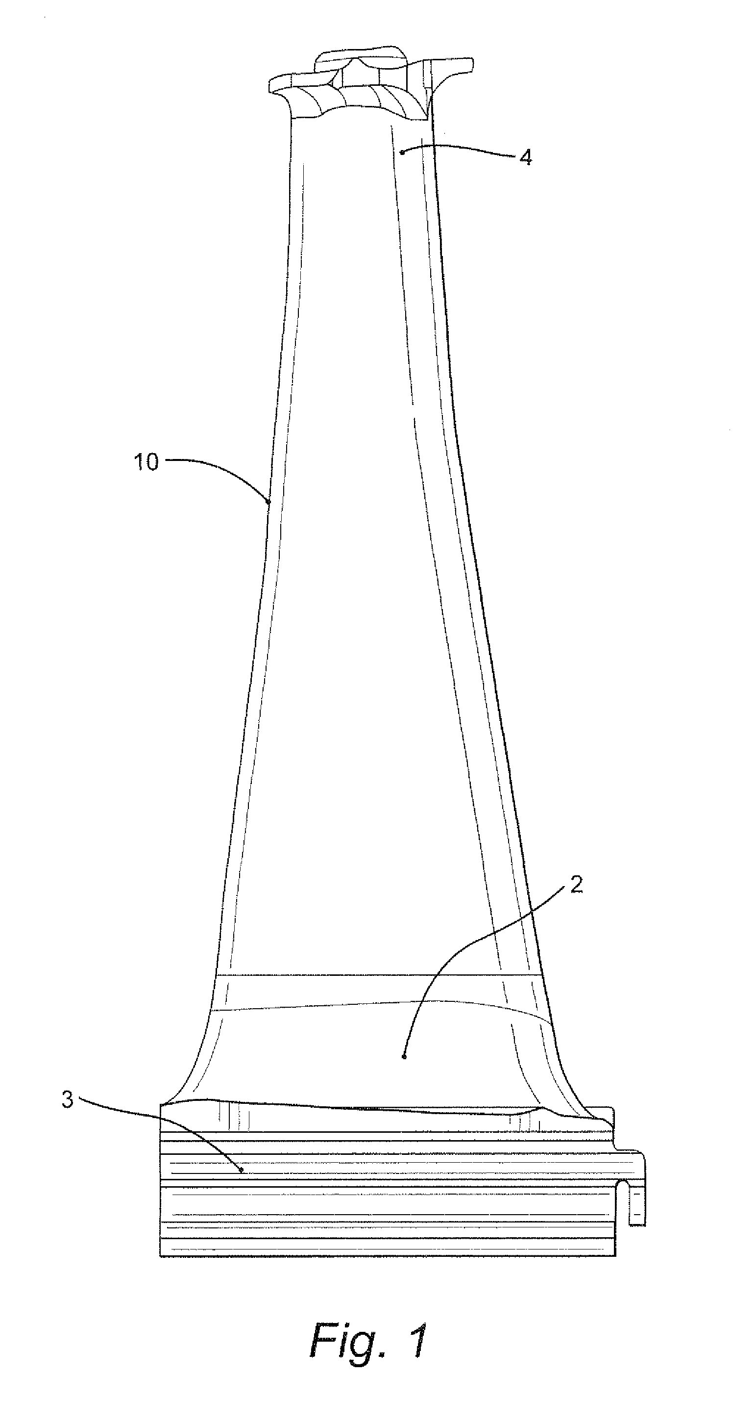
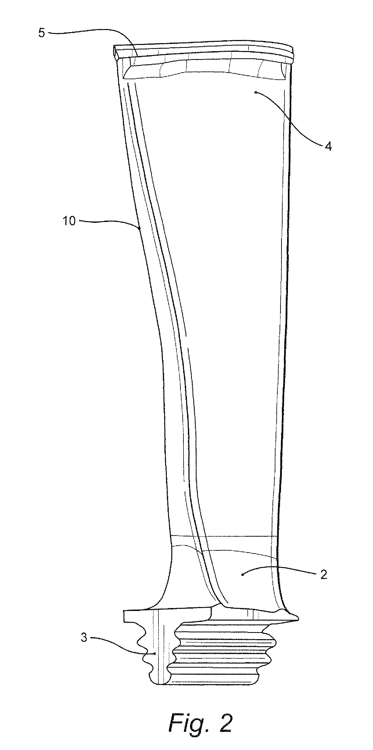
[0016]With reference to FIGS. 1 and 2, a rotating blade for a steam turbine includes a root section 2 connected to an axial entry dovetail 3 for connection to the turbine rotor. As shown, the dovetail 3 includes a two-hook fir tree shape. The subject of a co-pending U.S. patent application, the axial entry dovetail geometry has been optimized to obtain a distribution of average and local stress that guarantees adequate protection for over-speed and LCF (low cycle fatigue) margins.

[0017]An airfoil 10 extends from the root section 2, and a tip section 4 is continuous with the airfoil section 10. As shown in FIGS. 3 and 4, a cover 5 is formed as part of the tip section 4.

[0018]In order to accommodate operating speeds that range from 5625 to 11250 rotations per minute with a maximum mass flow of 30.9 kg / s and an exit annulus area of 0.461 m2, computational fluid dynamics were performed in order to optimize airfoil geometry. Mass flow and annulus area are important design parameters as i...


PUM


Abstract

A rotating blade for a steam turbine includes a root section and an airfoil section contiguous with the root section. The airfoil section is shaped to optimize aerodynamic performance while providing optimized flow distribution and minimal centrifugal and bending stresses. The blade also includes a tip section continuous with the airfoil section, and a cover formed as part of the tip section. The cover defines a radial seal that serves to minimize tip losses. The rotating blade is capable of running at operating speeds between 5626 and 11250 rotations per minute.

Description

BACKGROUND OF THE INVENTION[0001]The present invention relates to a rotating blade for a steam turbine and, more particularly, to a rotating blade for a steam turbine with optimized geometry capable of increased operating speeds.[0002]The steam flow path of a steam turbine is formed by a stationary cylinder and a rotor. A number of stationary vanes are attached to the cylinder in a circumferential array and extend inward into the steam flow path. Similarly, a number of rotating blades are attached to the rotor in a circumferential array and extend outward into the steam flow path. The stationary vanes and rotating blades are arranged in alternating rows so that a row of vanes and the immediately downstream row of blades form a stage. The vanes serve to direct the flow of steam so that it enters the downstream row of blades at the correct angle. The blade airfoils extract energy from the steam, thereby developing the power necessary to drive the rotor and the load attached to it.[000...

Claims


Application Information

Patent Timeline
28 Jan 2010
Publication
US20100021306A1
IPC
F01D5/14
CPC
F01D5/147; F05D2220/31; F01D5/225
Inventors
MUJEZINOVIC, AMIR; SLEPSKI, JONATHON