

Equilateral strand composite lumber and method of making same
a technology of composite lumber and equilateral strand, which is applied in the direction of structural elements, building components, textiles and paper, etc., can solve the problems of wood being in danger of losing significant market share to non-wood products, prone to shear failure zones, and no longer optimal composition
- Summary
- Abstract
- Description
- Claims
- Application Information
AI Technical Summary
Benefits of technology
Problems solved by technology
Method used
Image

Examples
first embodiment
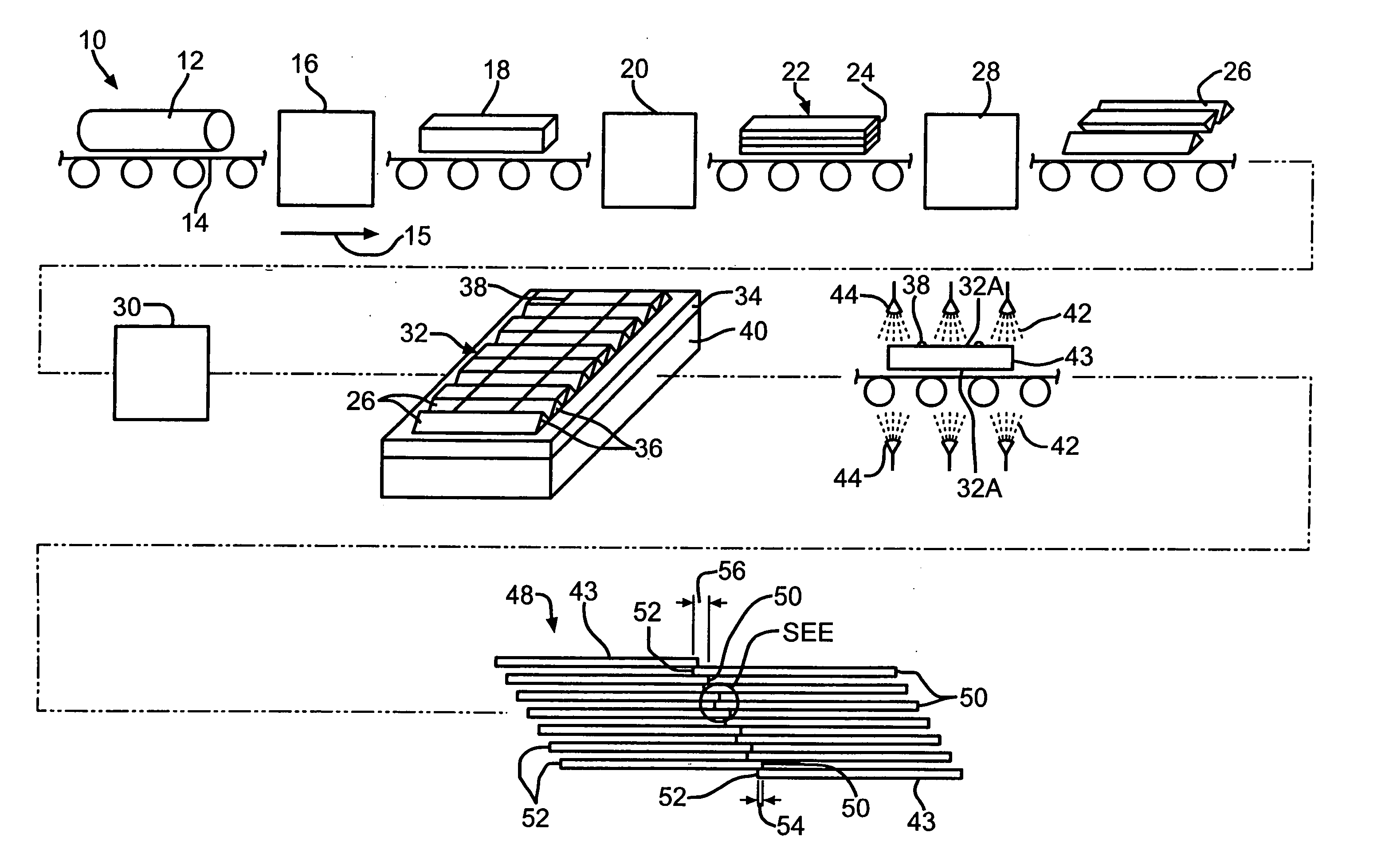
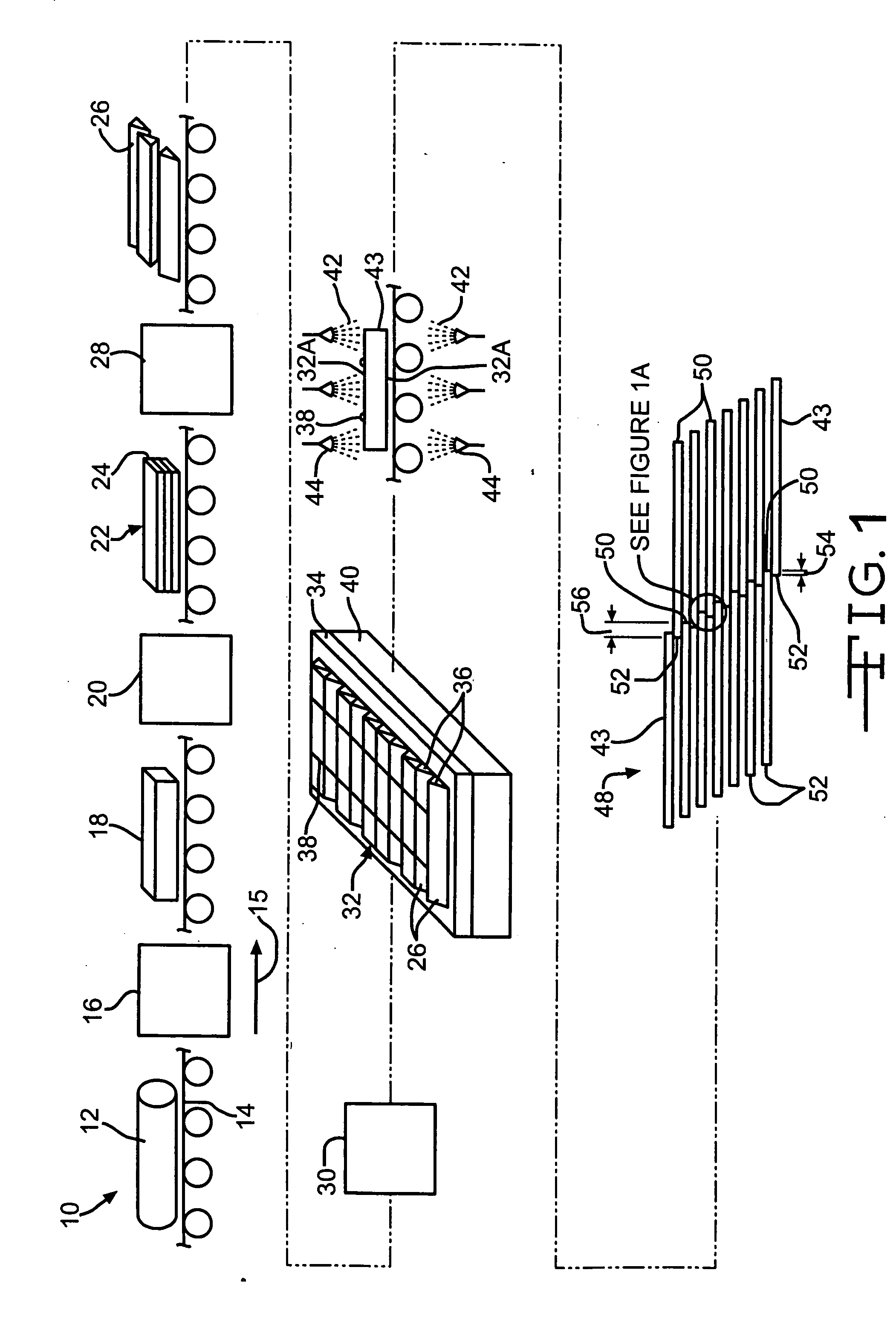
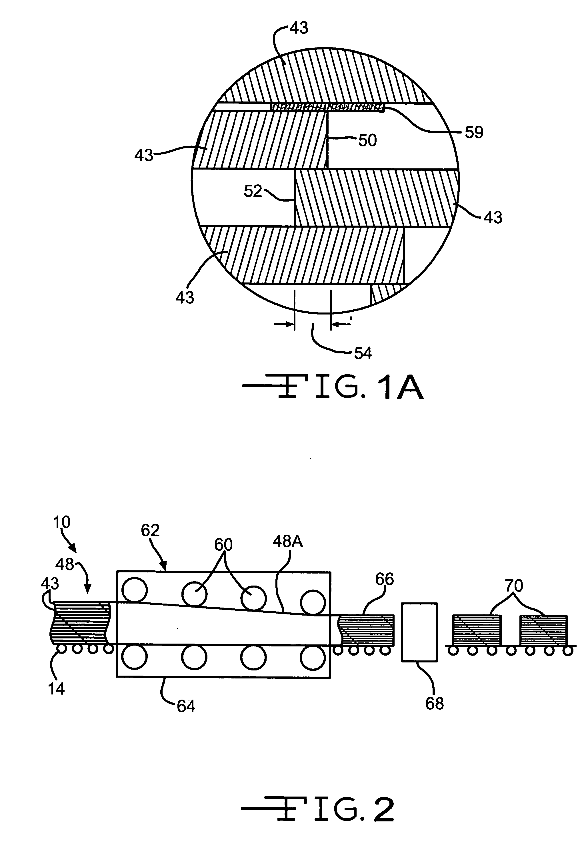
[0048] A plurality of resin-coated mats 43 are then stacked to define a laid-up billet 48. As used herein, laid-up billet is defined as the billet prior to being cured, as described herein below. a laid-up billet 48 is illustrated in FIG. 1. Preferably, the resin-coated mats 43 are stacked in a stepped arrangement such that a first end 50 of any mat 43 overlaps a second end 52 of the adjacent lower mat 43, thereby defining a lap-joint 54. Preferably, first end 50 overlaps the second end 52 by about two inches. The resin-coated mats 43 are further stacked such that the first end 52 of any mat 43 overlaps the end 50 of the adjacent lower mat 43, thereby defining an overlap region 56. Although 14 mats 43 are shown in the exemplary embodiment of the laid-up billet 48 illustrated in FIG. 1, it will be understood that any other desired number of mats 43 can be stacked to define the laid-up billet 48. The lay-up method, as described above, is well known in the art.
[0049] If desired, a laye...
second embodiment
[0050] laid-up billet 48′ is illustrated in FIG. 8. The laid-up billet 48′ is substantially identical to the laid up billet 48, and includes a plurality of the mats 43. In the laid-up billet 48′ however, the first and second ends 50 and 52, respectively, of the mats 43 do not overlap, but abut one another. This practice is well known in the art.
[0051] If desired at least one surface 33A of at least one end of the mats 32 can be beveled or scarfed, as best shown in FIG. 9. The practice of scarfing is well known in the art. Alternately, two surfaces 33B and 33C, respectively, of at least one end of the mats 32 can be scarfed, as best shown in FIG. 10. Such scarfing minimizes void space which can occur after curing at either or both of the lap joints 54 and the overlap regions 56. The scarfing further minimizes the potential density profile of the cured billet 66 at the lap-joints 54 and the overlap regions 56; i.e. scarfing increases density of the cured billet at the lap-joints 54 an...
third embodiment
[0052] laid-up billet 48″ is illustrated in FIG. 11. The laid-up billet 48″ includes a plurality the mats 43. The mats 43 are preferably stacked such that the first ends 50 of the mats 43 are vertically aligned.
[0053] If desired, a laid-up billet can include stands having a plurality of sizes. For example, strands having equilateral triangle cross-sections and side lengths S1 of about {fraction (1 / 4)} inch and about {fraction (7 / 16)} inch can be used to form a laid-up billet. It is believed that once cured, billets having strands with a plurality of sizes will be stronger than billets made with strands of only one size. It has been shown, for example, that composite beams made from triangular cross-sectional strands having a side length of about ¼ inch have a higher shear strength than composite beams made from strands having a side length of about {fraction (7 / 16)} inch. Additionally, composite beams made from strands having a side length of about {fraction (7 / 16)} inch have a high...
PUM
| Property | Measurement | Unit |
|---|---|---|
| Length | aaaaa | aaaaa |
| Time | aaaaa | aaaaa |
| Fraction | aaaaa | aaaaa |
Abstract
Description
Claims
Application Information