Evaporator for refrigeration systems

a technology of evaporator and refrigeration system, which is applied in the direction of defrosting, lighting and heating apparatus, domestic cooling apparatus, etc., can solve the problems of low heat transfer efficiency and ice formation in the evaporator, and achieve the effect of significantly affecting the thermal exchange efficiency and higher level of ice formation

Inactive Publication Date: 2005-01-06
MULTIBRAS SA ELETRODOMESTICOS
View PDF6 Cites 17 Cited by
  • Summary
  • Abstract
  • Description
  • Claims
  • Application Information

AI Technical Summary

Benefits of technology

[0013] According to the invention, the fins 10, which are incorporated to the first and second tubes 20, according to the direction of the forced air flow F, are spaced from each other by a larger distance d, when they are operatively associated with a refrigerating environment, and by a smaller distance d, when they are operatively associated with a freezing environment. Said distances d decrease at each two subsequent tubes 20, until reaching at least the third tube 20, said distance being then maintained at a minimum value for the other subsequent tubes 20. The constructive arrangement proposed by the present invention allows obtaining an optimum coefficient of thermal exchange for the evaporator, which can have its fins arranged to operate with forced airflows circulating through different environments to be refrigerated, with the arrangement being made so that a higher level of ice formation in the evaporator region is supported without significantly affecting the thermal exchange efficiency.

Problems solved by technology

However, since the heated air to be forced through the evaporator contains humidity in a higher or lower degree as a function of the operation to which the environment to be refrigerated is submitted, this humidity tends to condensate, causing the formation of ice in the evaporator.
The result of this arrangement is the provision of an evaporator that requires less frequent defrost operations, but which operates with low efficiency in terms of heat transfer.

Method used


Image

  • Evaporator for refrigeration systems
  • Evaporator for refrigeration systems
  • Evaporator for refrigeration systems

Examples


Embodiment Construction

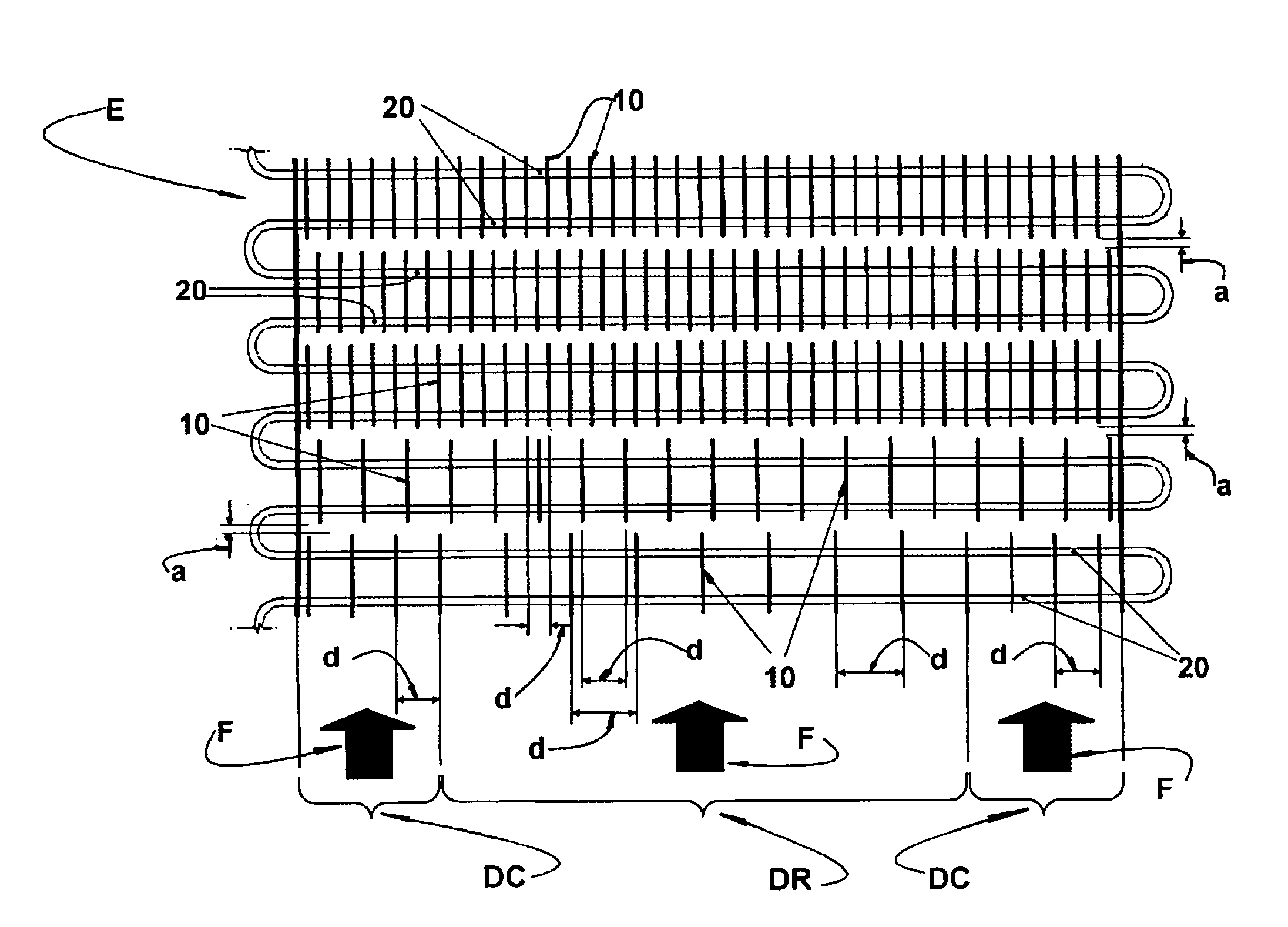
[0020] As illustrated in FIGS. 1 and 6, the evaporator E of the present invention comprises a plurality of fins 10 arranged in multiple rows, extending transversally to the direction of a forced airflow F that is forced to pass through the evaporator E, as well as through one or more environments to be refrigerated (not illustrated) and which can be defined, for example, by a refrigerating environment, such as the compartment of a refrigerator, which is refrigerated at a temperature of about 5° C. to about 0° C., and by a freezing environment, such as the compartment of a freezer, which is refrigerated at a temperature of about −10° C. to about −20° C.

[0021] The forced airflow F is produced by a fan (not illustrated), which is adequately mounted in series with the air circulation to be produced through the evaporator and through the respective environment(s) to be refrigerated.

[0022] The fins 10 are obtained from a plate made of a material of high thermal conductivity, with a thic...


PUM


Abstract

An evaporator for refrigeration systems, comprising a set of tubes (20) arranged in series, spaced and parallel in relation to each other, carrying a refrigerant fluid and which are incorporated to and trespass a plurality of fins (10) arranged in multiple rows extending transversally to the direction of a forced airflow (F). The fins (10), which are incorporated to the first and second tubes (20) are spaced from each other by a larger distance (d), when they are operatively associated with a refrigerating environment, and by a smaller distance (d), when they are operatively associated with a freezing environment. Said distances (d) decrease at each two subsequent tubes (20), until reaching at least the third tube (20), said distance being then maintained at a minimum value for the other subsequent tubes (20).

Description

FIELD OF THE INVENTION [0001] The present invention refers to the construction of an evaporator for refrigeration systems, more particularly to the arrangement of the fins of an evaporator of the tube-fin type for refrigeration systems with forced ventilation, generally used in refrigerators, freezers and other refrigeration appliances. BACKGROUND OF THE INVENTION [0002] The refrigeration systems with forced ventilation usually applied to refrigerators and freezers, generally use a compact evaporator of the tube-fin type comprising a plurality of fins incorporated to and trespassed by a set of tubes arranged in series in the form of a coil and carrying a refrigerant fluid. A forced airflow is forced to pass through the evaporator, which airflow is drawn from the inside of an environment to be cooled, in order to be refrigerated by the evaporator and discharged back to the interior of said environment, as it occurs for example in the refrigerating or freezing compartments of a refrig...

Claims


Application Information

Patent Timeline
Patent Type & Authority Applications(United States)
IPC IPC(8): F25B39/02F25B47/00F28D1/047F28F1/32
CPCF25B39/02F25B47/006F28F1/32F28D1/0477F25B2500/01
Inventor SCHMID, ALEXANDRE CURYSALLES, JOSE ALBERTO CORREA
Owner MULTIBRAS SA ELETRODOMESTICOS
Why Eureka
Try Eureka