Aerodynamically shaped static pressure sensing probe

a static pressure sensing and aerodynamic technology, applied in the field of aerodynamically shaped static pressure sensing probes, can solve the problems of increasing drag, weight, and requiring substantial amounts of heating power for probes, and achieving the effect of enhancing the accuracy of the sensed pressur

Inactive Publication Date: 2005-01-06
ROSEMOUNT AEROSPACE
View PDF11 Cites 17 Cited by
  • Summary
  • Abstract
  • Description
  • Claims
  • Application Information

AI Technical Summary

Benefits of technology

Because the ports can be located just outside the boundary layer on the surface of the aircraft, and the port position with respect to the corrugations can also be adjusted, the accuracy of the sensed pressure is enhanced and the vertical separation minimum requirements for aircraft can be achieved.

Problems solved by technology

The strut mounted probes as shown in the prior art add drag, and weight, and while reliable, the desirability of having small, lightweight, low drag probes that will withstand reasonable impacts exists.
The strut mounted pitot static probes that are used do extend outside the boundary layer, but the strut mounted probes also require substantial amounts of power for heating to prevent icing.
Since a strut is used, there is relatively high drag and weight.
The increasing demands on accuracy in maintaining vertical separation for the flight levels for civil aircraft under positive control of the air traffic control system have required greater accuracy in sensing static pressure, and flush sensor plates with static ports generally do not meet these accuracy requirements.

Method used


Image

  • Aerodynamically shaped static pressure sensing probe
  • Aerodynamically shaped static pressure sensing probe
  • Aerodynamically shaped static pressure sensing probe

Examples


Embodiment Construction

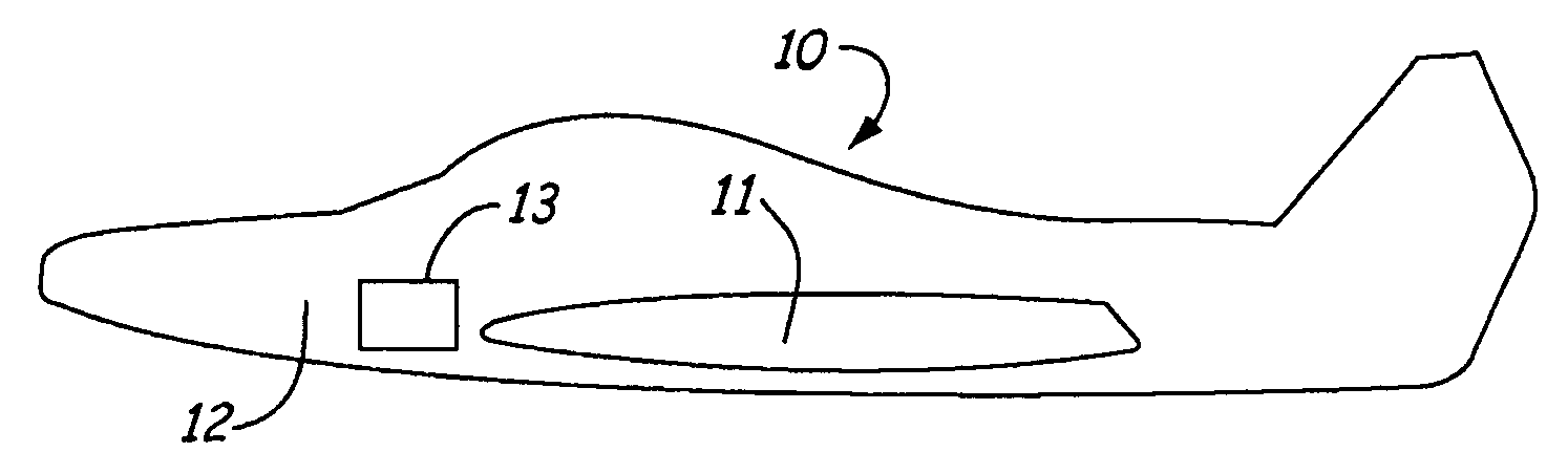
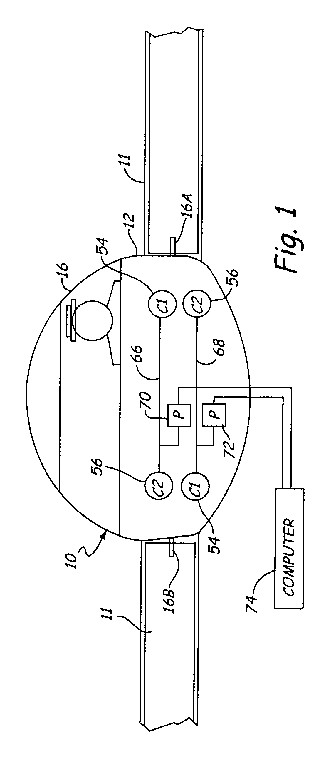
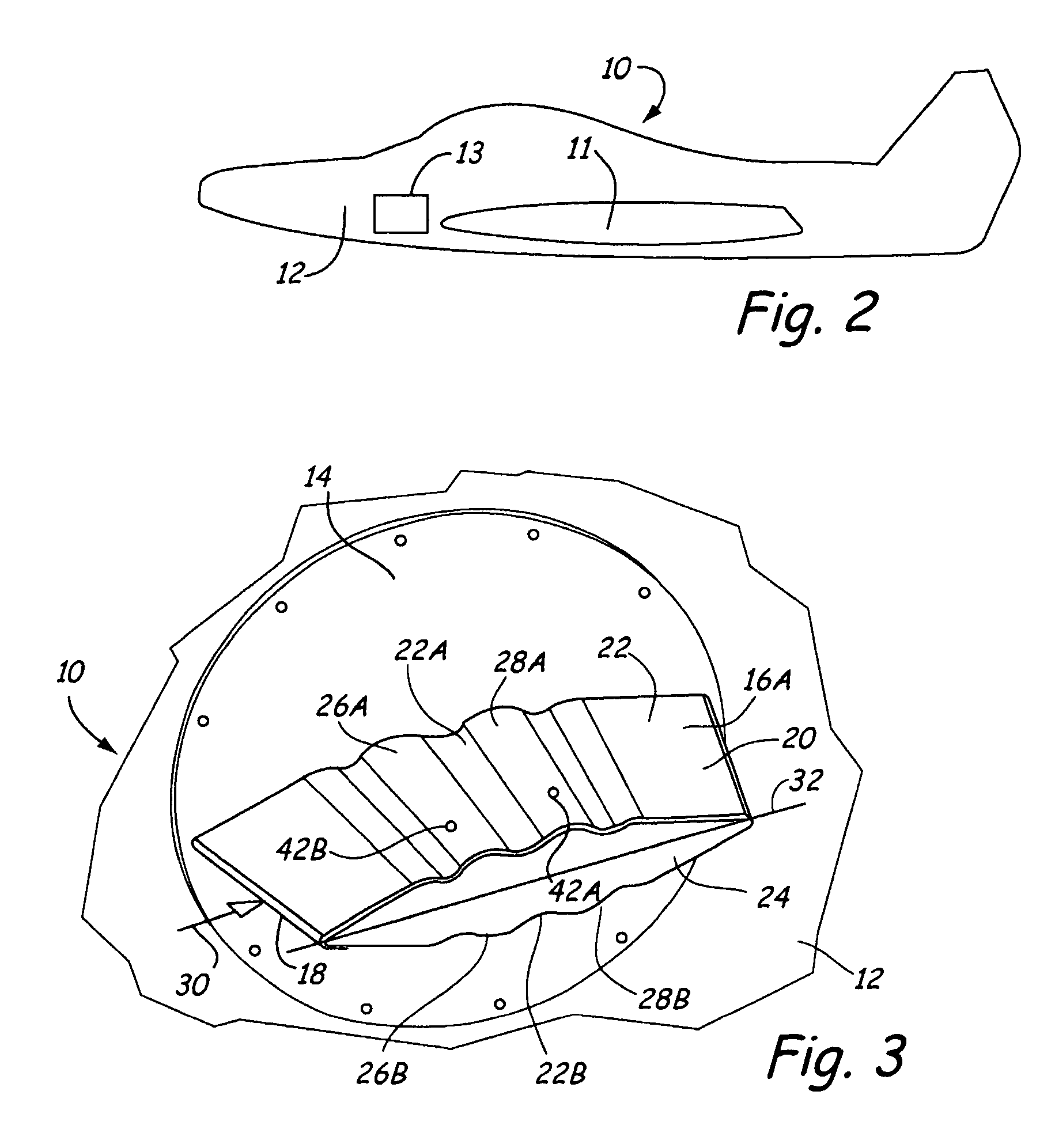
Referring to FIGS. 1 and 2, an aircraft indicated generally at 10 is shown with only a fragmentary portion illustrated. The aircraft skin 12 is used to mount two static sensing probes 16A and 16B made according to the present invention. The probes are on opposite sides of the aircraft ahead of the aircraft wings 11. A mounting base plate 14 (FIGS. 3 and 4) mounts the respective static sensing probe to the aircraft skin. In FIGS. 3 and 4, probe 16A is illustrated, but probe 16B is construed as a mirror image of probe 16A. The static sensing probes 16A and 16B each have an aerodynamically shaped cross section, as shown in FIG. 5, and include a relatively thin, rounded leading edge 18, a trailing edge 20, an upper surface 22 on an upper wall 22A and a lower surface 24 on a lower wall 24A. Portions of the upper and lower surfaces adjacent the leading and trailing edges that is, ahead of or behind the ridges are convex surfaces that are a general airfoil shape.

The corrugations are for...


PUM


Abstract

A static pressure sensing probe has an aerodynamically shaped cross section, and extends laterally from an aircraft surface sufficiently so that an outer end of the probe is a short distance outside the boundary layer on the aircraft surface on which the probe is mounted. The probe has surface corrugations or ridges along the probe, and the ridges include an upstream ridge adjacent the leading edge, and a downstream ridge spaced rearwardly from the upstream ridge. The ridges cause pressure disturbances along the probe surfaces. Static pressure sensing ports are positioned on the surfaces of the probe relative to the ridges in regions of pressure disturbances caused by the ridges. The probes can be mounted on opposite sides of the aircraft and pneumatically or electrically connected to average the pressures from selected sets of ports.

Description

BACKGROUND OF THE INVENTION The present invention relates to an aerodynamically shaped, aircraft mounted static pressure sensing probe that extends a short distance outwardly beyond the boundary layer on the surface of the aircraft, and provides reliable static pressure measurements, with a low drag configuration. Various static pressure sensing probes have been advanced in the prior art, some of which include configurations that modify the static pressure sensed at locations along the probe. U.S. Pat. No. 4,730,487 shows a strut mounted probe, that has static pressure sensing ports on the surface, with pressure modifying surface irregularities provided. A strut mounted dual static tube or probe is shown in U.S. Pat. No. 3,482,445. The strut mounted probes as shown in the prior art add drag, and weight, and while reliable, the desirability of having small, lightweight, low drag probes that will withstand reasonable impacts exists. The probes also need to provide reliable static p...

Claims


Application Information

Patent Timeline
Patent Type & Authority Applications(United States)
IPC IPC(8): B64D43/02G01P5/165G01P13/02
CPCB64D43/02G01P13/025G01P5/165
Inventor FOSTER, ROGER D.HEINE, PAUL F.MOYNIHAN, PATRICK J.OWENS, DAVID G.
Owner ROSEMOUNT AEROSPACE
Why Eureka
Try Eureka