Valve stem seal assembly

a valve stem and seal technology, applied in the direction of valve details, valve arrangements, spindle sealings, etc., can solve the problems of reducing the axial clearance and affecting the sealing effect of the valve stem,

Inactive Publication Date: 2005-01-06
DANA AUTOMOTIVE SYST GRP LLC
View PDF9 Cites 35 Cited by
  • Summary
  • Abstract
  • Description
  • Claims
  • Application Information

AI Technical Summary

Problems solved by technology

Because temperatures in the combustion chamber may approach or exceed 1000 degrees Centigrade, any lubricating oil exposed to these temperatures will vaporize or burn leaving behind deposits that may interfere with the proper sealing of the valves and cause rapid deterioration.
Also, excessive burned or unburned oil in the exhaust stream may worsen engine exhaust emissions.
Restrictions in the geometry of engines sometimes do not allow enough axial (vertical) clearance to properly design a top-sealing valve stem seal assembly nor do they allow enough radial (horizontal) clearance to design a valve stem seal assembly that properly seals around the guide.

Method used


Image

  • Valve stem seal assembly
  • Valve stem seal assembly
  • Valve stem seal assembly

Examples


Embodiment Construction

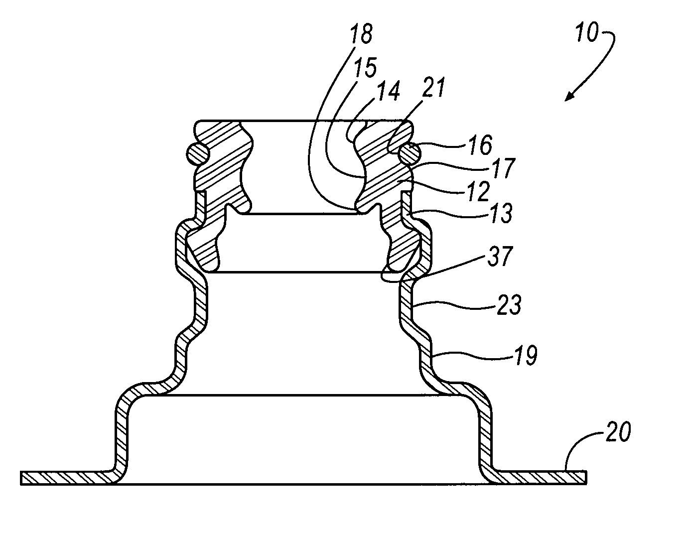
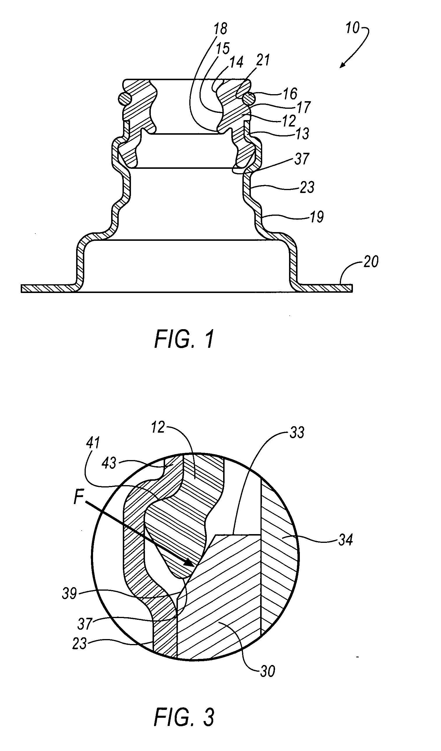
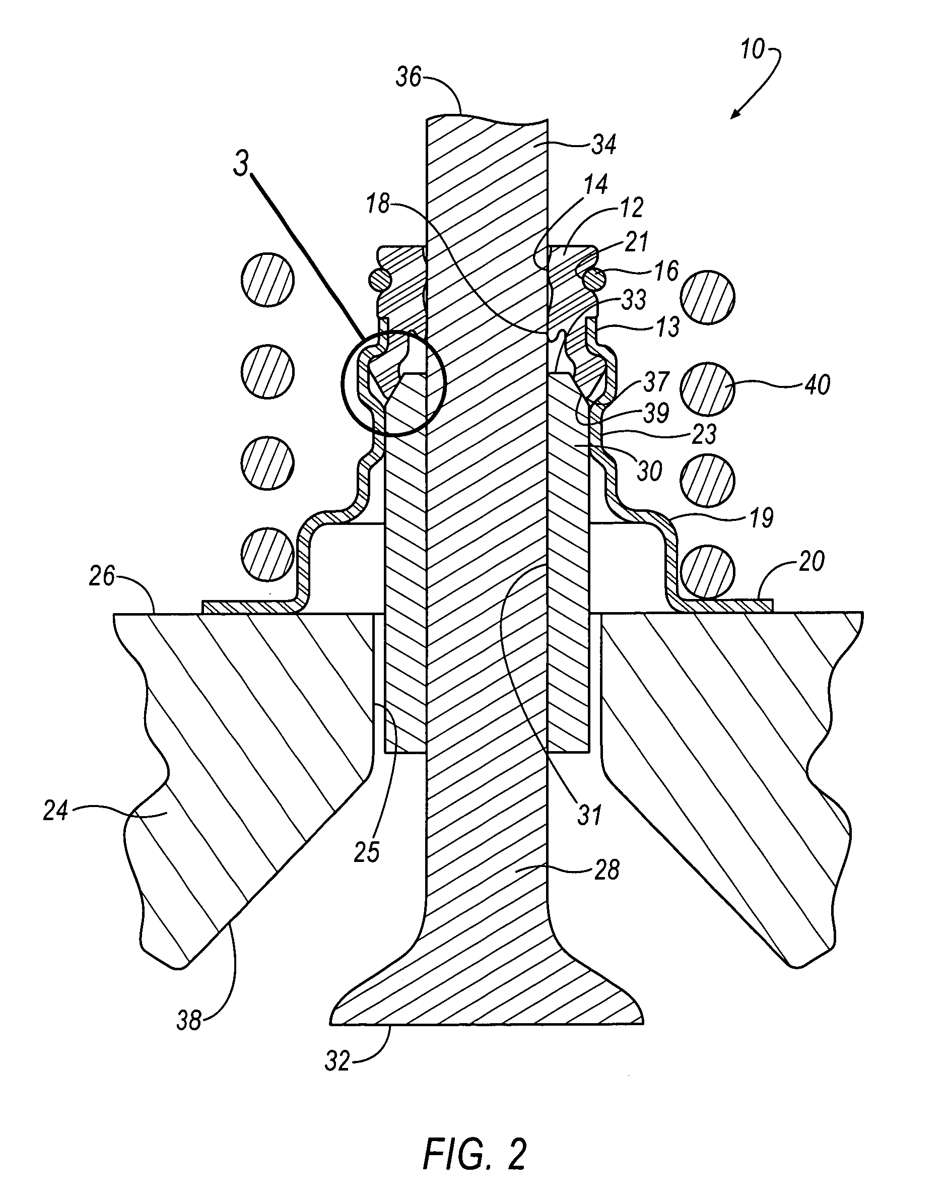
[0010] Referring initially to FIG. 1, a valve stem seal assembly 10 incorporates an elastomeric valve sealing element or valve stem seal 12 affixed or otherwise assembled to a cylindrical retainer 19. The sealing element 12 may be affixed to the retainer 19, for example, an end wall 13 of the retainer 19 by bonding, or the like. Although the invention contemplates that the retainer 19 is formed of metal, other materials may be suitable depending upon the harshness of the particular environment. For example, some glass-filled nylons or other plastics may be suitable for some engine environments, wherein in such cases the retainer might suitably be formed of plastic materials.

[0011] The sealing element 12 has a generally cylindrical body that includes interior and exterior surfaces 15 and 17, respectively. The sealing element 12 is supported in the end wall 13 by means of an exterior groove 21 formed in the exterior surface 17 of the sealing element 12. The interior surface 15 of the...


PUM


Abstract

A valve stem seal assembly includes a retainer and a sealing element disposed within the retainer. The retainer includes a step and one or more installation pads. The sealing element includes a first sealing lip for sealing a valve stem, and a second sealing lip for sealing a chamfer of a valve guide. The step of the retainer exerts a compression force, F, against the second sealing lip to seal the second sealing lip against the chamber of the valve guide. The one or more installation pads exerts a frictional force against the valve guide to prevent movement of said valve stem seal assembly. It is emphasized that this abstract is provided to comply with the rules requiring an abstract that will allow a searcher or other reader to quickly ascertain the subject matter of the technical disclosure. It is submitted with the understanding that it will not be used to interpret or limit the scope or meaning of the claims. 37 CFR 1.72(b).

Description

TECHNICAL FIELD [0001] The present invention relates to a valve stem seal assembly, and in particular to a valve stem seal assembly with a sealing element for sealing the valve guide chamfer. BACKGROUND OF THE INVENTION [0002] Those skilled in the art will appreciate the manner in which intake and exhaust valves are employed in cylinder heads of internal combustion engines. In conventional overhead valve internal combustion engines, a pair of valves reciprocates in timed alternation to provide intermittent communication between the intake and exhaust manifolds and a combustion chamber. As is well known, the intake port of a combustion chamber is opened and closed by the reciprocating motion of at least one intake valve. The intake valve permits fuel mixed with air to flow into the combustion chamber. In addition, an internal combustion engine has at least one exhaust valve and associated exhaust port for releasing expended combustion gases into the atmosphere. Lubrication is provide...

Claims


Application Information

Patent Timeline
Patent Type & Authority Applications(United States)
IPC IPC(8): F01L3/08F16K41/10
CPCF01L3/08F16K41/10F01L2101/00F01L2301/00
Inventor MC ARTHY, TROY D.HEGEMIER, TIMOTHY A.
Owner DANA AUTOMOTIVE SYST GRP LLC
Why Eureka
Try Eureka