Temperature sensing device in an integrated circuit

a temperature sensing device and integrated circuit technology, applied in the field of oscillators, can solve the problems of wasting power, increasing the weight and expense of electronic devices, and losing the ability of cells to hold a charg

Inactive Publication Date: 2005-01-06
ROUND ROCK RES LLC
View PDF7 Cites 25 Cited by
  • Summary
  • Abstract
  • Description
  • Claims
  • Application Information

AI Technical Summary

Benefits of technology

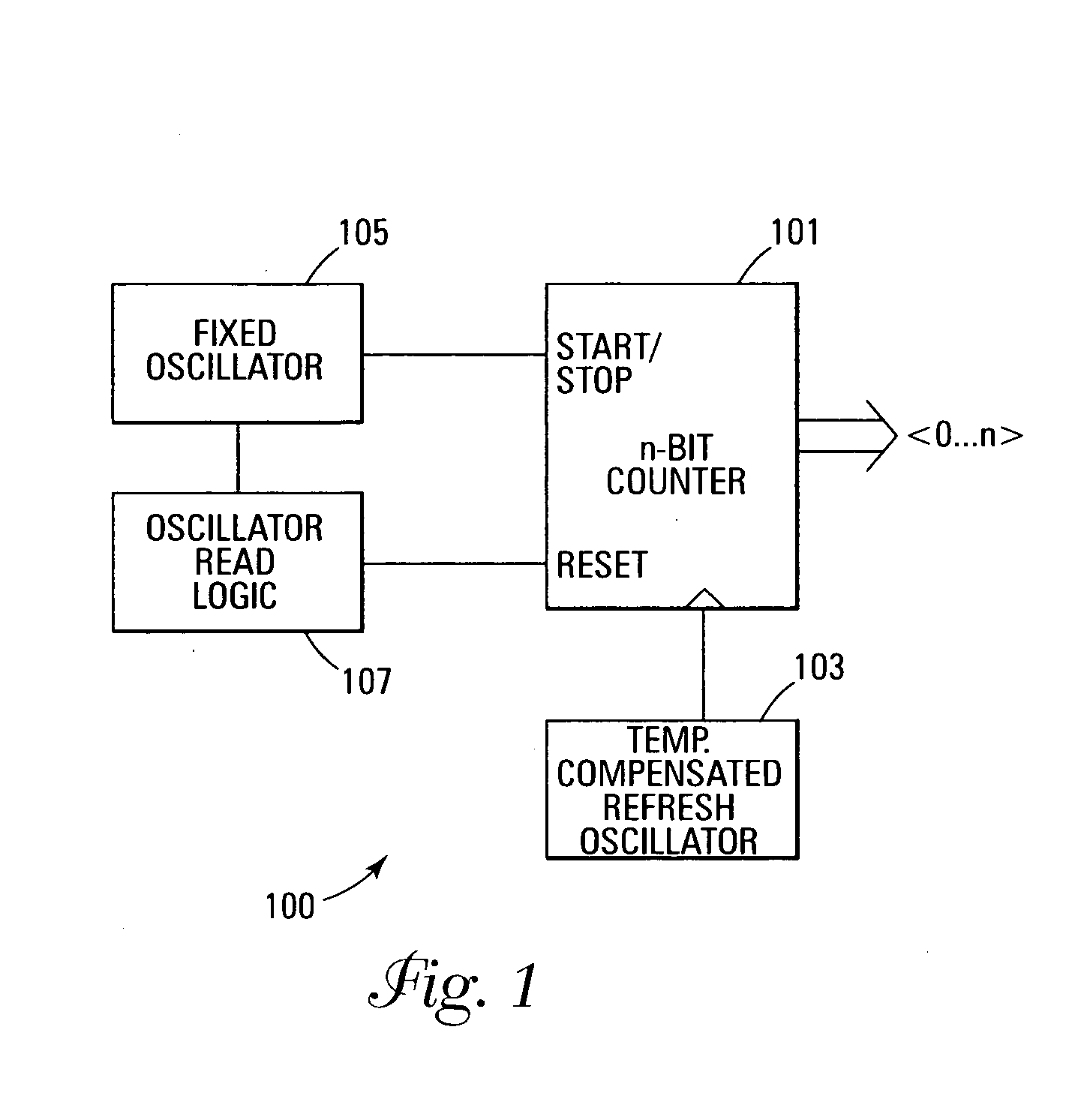
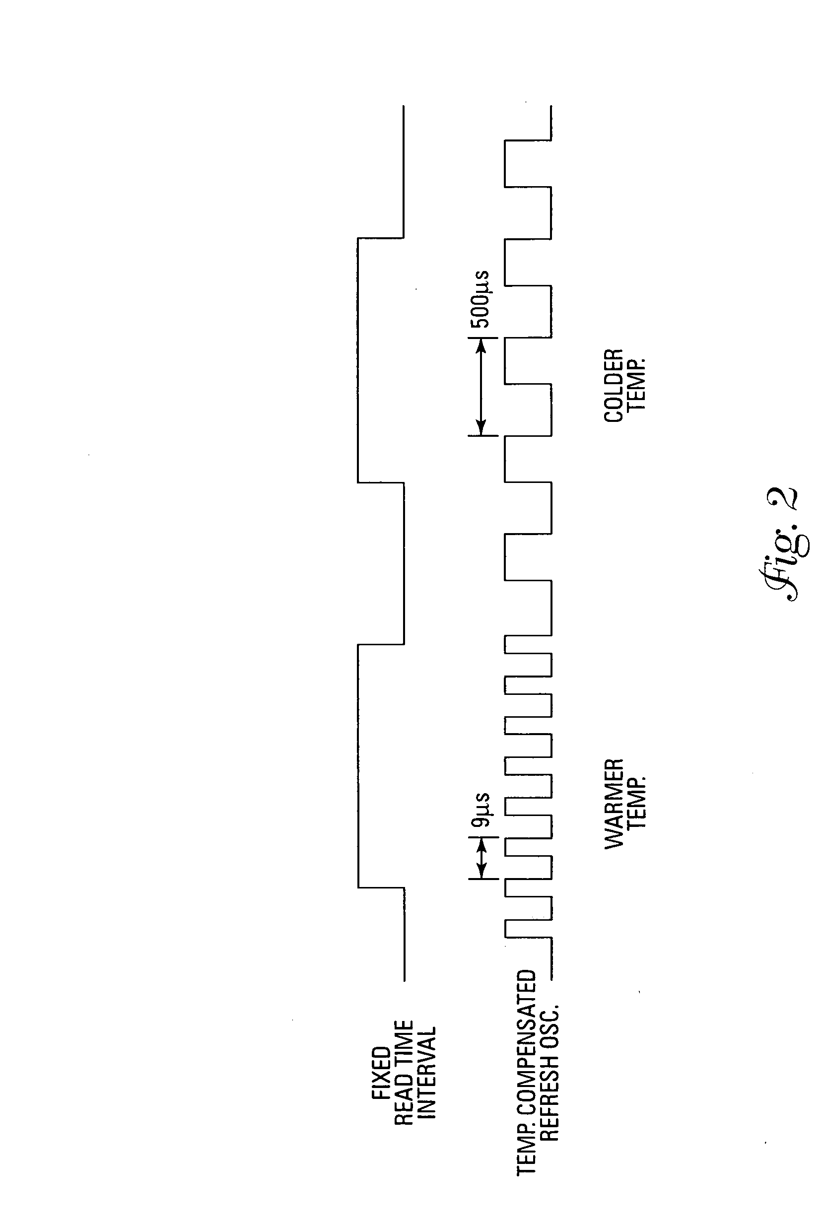
[0008] In one embodiment, the variable rate signal is a clocking signal to the counter and the fixed width signal is used to enable / disable the counter. While the counter is enabled, the faster the variable rate signal clocks the counter, the larger the count that occurs during the sense cycle. The larger count indicates a warmer temperature. The smaller the count, the colder the indicated temperature.

Problems solved by technology

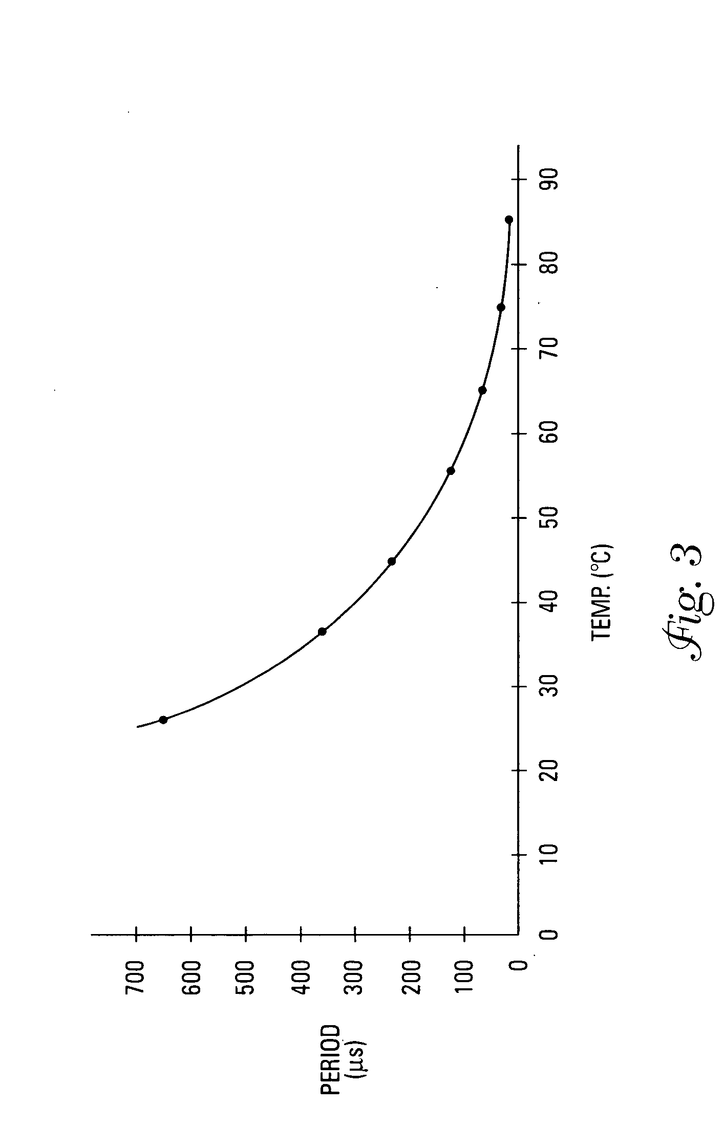
As the device heats up, the cells lose their ability to hold a charge due to current leakage.
However, the faster refresh rate is not required when the device is operating at a cooler temperature, thus wasting power.
Such devices typically require at least one external temperature sensor that adds to the weight and expense of the electronic device.

Method used


Image

  • Temperature sensing device in an integrated circuit
  • Temperature sensing device in an integrated circuit
  • Temperature sensing device in an integrated circuit

Examples


Embodiment Construction

[0017] In the following detailed description of the invention, reference is made to the accompanying drawings that form a part hereof, and in which is shown, by way of illustration, specific embodiments in which the invention may be practiced. In the drawings, like numerals describe substantially similar components throughout the several views. These embodiments are described in sufficient detail to enable those skilled in the art to practice the invention. Other embodiments may be utilized and structural, logical, and electrical changes may be made without departing from the scope of the present invention. The following detailed description is, therefore, not to be taken in a limiting sense, and the scope of the present invention is defined only by the appended claims and equivalents thereof.

[0018]FIG. 1 illustrates a block diagram of one embodiment of a temperature sensing device 100 of the present invention. An n-bit counter 101 generates a count that indicates the temperature s...


PUM

PropertyMeasurementUnit
timeaaaaaaaaaa
temperatureaaaaaaaaaa
frequencyaaaaaaaaaa

Abstract

A temperature sensing device can be embedded in a memory circuit in order to sense the temperature of the memory circuit. One oscillator generates a temperature variable signal that increases frequency as the temperature of the oscillator increases and decreases frequency when the temperature of the oscillator decreases. A temperature invariant oscillator generates a fixed width signal that is controlled by an oscillator read logic and indicates a temperature sense cycle. An n-bit counter is clocked by the temperature variable signal while the fixed width signal enables/inhibits the counter. The faster the counter counts, the larger the count value at the end of the sense cycle indicated by the fixed width signal. A larger count value indicates a warmer temperature. A smaller count value indicates a colder temperature.

Description

TECHNICAL FIELD OF THE INVENTION [0001] The present invention relates generally to oscillators and in particular the present invention relates to variable rate oscillators having temperature variable frequencies. BACKGROUND OF THE INVENTION [0002] It is sometime desirable to know the internal temperature of integrated circuits. For example, dynamic random access memory (DRAM) devices require periodic refresh cycles in order to maintain the integrity of the data stored in the memory. The temperature of the memory device affects the frequency at which the memory device needs to be refreshed. As the device heats up, the cells lose their ability to hold a charge due to current leakage. Therefore, the warmer the device the more often it has to be refreshed. [0003] Designers typically take into account the worst case requirement for refreshing a DRAM and design the memory to refresh at a fixed rate consistent with the maximum operating temperature of the part. However, the faster refresh ...

Claims


Application Information

Patent Timeline
Patent Type & Authority Applications(United States)
IPC IPC(8): G01K1/02H02J7/04
CPCG01K1/02G01K1/20H02J7/007H02J7/0052G01K13/00H02J7/00
Inventor LOVETT, SIMON J.
Owner ROUND ROCK RES LLC
Why Eureka
Try Eureka