
Apparatus for the detection of photons of a light beam having a three-dimensional array of detectors

a technology of three-dimensional array and detector, which is applied in the field of fluorescence microscopy, can solve the problems of large time-consuming and laborious, large amount of equipment, and large amount of equipment, and achieve the effect of increasing the maximum counting rate processible by the detection device and high photon flux

Inactive Publication Date: 2007-08-21
LEICA MICROSYSTEMS CMS GMBH
View PDF8 Cites 0 Cited by
  • Summary
  • Abstract
  • Description
  • Claims
  • Application Information

AI Technical Summary

Benefits of technology

[0006]It is an object of the present invention to provide a device for detecting photons of a light beam emanating from a spatially limited source using simple means in a way that will enable a higher photon flux to be detected by the detection device, i.e., the maximum counting rate processible by the detection device to be increased.
[0009]The luminous intensity and, associated therewith, the recording speed may be increased by the device according to the present invention in a fluorescence microscope, for example, enabling the images to be created at a faster rate and, thus, even rapidly occurring biological or biochemical reactions in a sample to be made visible. It is likewise possible to achieve a higher image quality in the same recording time, due to increased photon statistics. When n detectors are used, the maximum possible counting rate increases by factor n, and the signal-to-noise ratio improves correspondingly by factor √n.
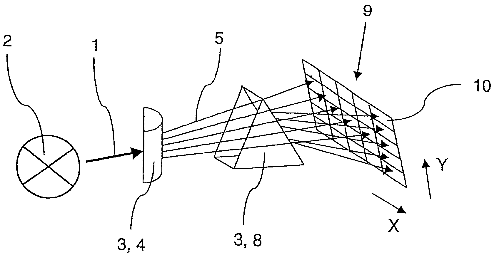
[0013]A compact design may be provided by arranging the detectors in an array. In the simplest embodiment, this may be a one-dimensional array, for example, in the sense of a linear row array. A broader photon distribution may be achieved by providing a planar array, in which the detectors are arranged in rows and columns.
[0015]The light beam maybe split in different ways. A splitting process which produces a statistical distribution of the photons is conceivable, for example. Such a photon distribution is able to be easily achieved by a simple defocusing of the light beam, for example by refracting the light beam using a cylindrical lens.
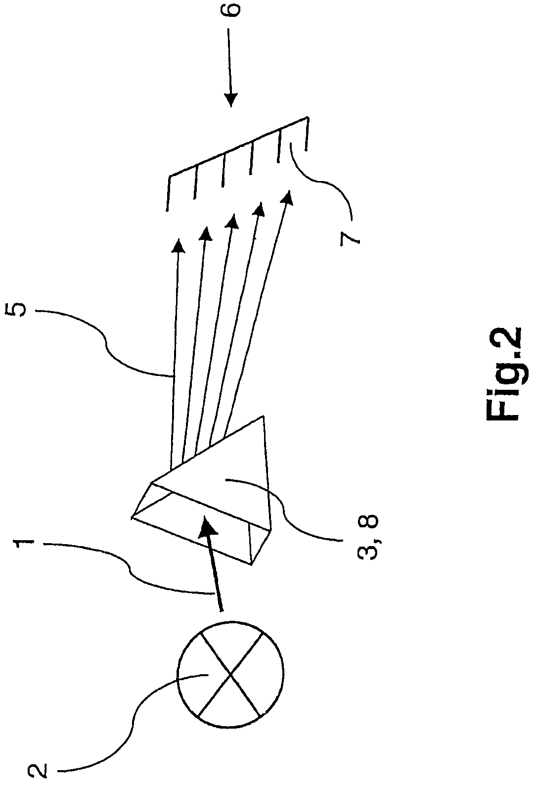
[0017]Besides the components just mentioned for splitting the light beam, in principle, electrooptical elements or electromechanical scanners may also be used. In particular, it is also possible to place a plurality of different components one behind the other in the light beam. This makes it possible to obtain very specific photon distribution patterns, such as, initially a defocusing in one direction to be followed by a spectral splitting in a direction orthogonal thereto.

Problems solved by technology

When operating a detector in the photon counting mode, the detector's dead time, or delay, is generally problematic.
As a result, a relatively long period of time is needed to record images of a high quality, i.e., to obtain adequate photon statistics.
Consequently, rapid biochemical processes in the sample which take place on a time scale that is faster than that of the image recording, are not accessible to conventional fluorescence microscopes.

Method used


Image

  • Apparatus for the detection of photons of a light beam having a three-dimensional array of detectors
  • Apparatus for the detection of photons of a light beam having a three-dimensional array of detectors
  • Apparatus for the detection of photons of a light beam having a three-dimensional array of detectors

Examples


Embodiment Construction

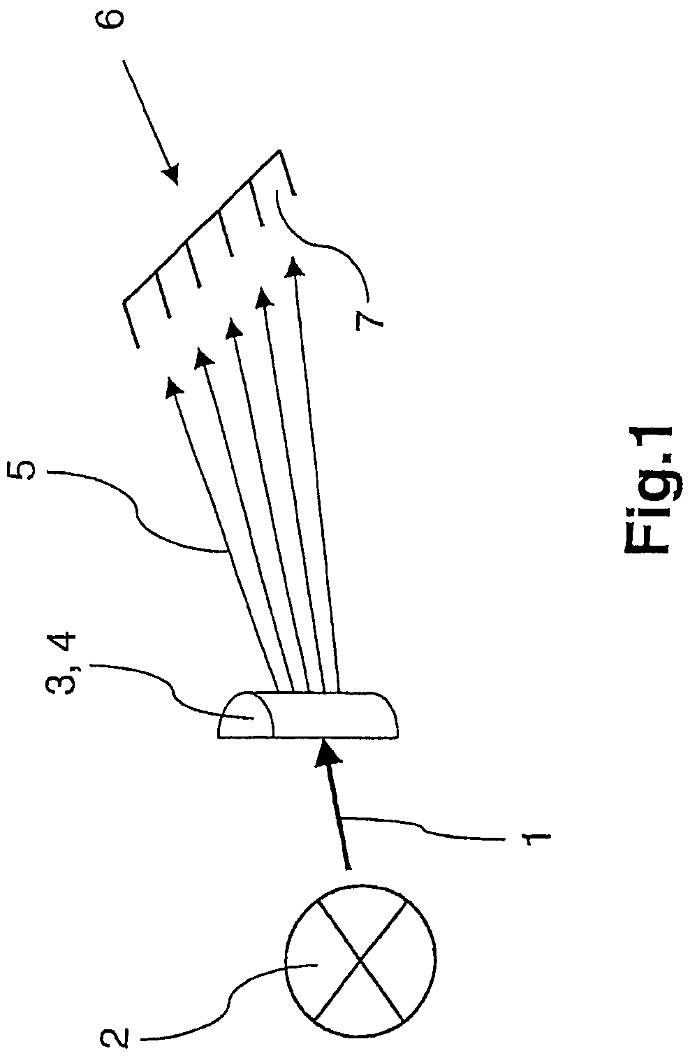
[0025]FIG. 1 depicts a light beam 1 emanating from a spatially limited light source 2; specifically, light source 2 may be a biological sample material excited to emit fluorescence. Light beam 1 impinges on an optical component 3 which is made of a transparent material and is designed as a semicylindrical lens 4. Light beam 1 propagates through cylindrical lens 4 and, upon emergence from lens 4, is defocused due to refraction, thereby producing a divergent light beam 5 within a plane of illumination, whose surface normal is the cylinder axis. The photons are statistically distributed within the plane of illumination.

[0026]Widened light beam 5 then impinges on a detection device which includes a plurality of detectors 7 that form an array 6. FIG. 1 shows exemplarily merely five detectors 7, which are combined to form a one-dimensional array 6. Since the photons of light beam 1 are not detected in one detector, but rather are uniformly distributed over altogether five detectors 7, the...


PUM


Abstract

An apparatus for detecting photons of a light beam emanating from a spatially limited source includes a detection device having a plurality of detectors forming a three-dimensional array with semitranslucent EMCCDs disposed one behind another. A light splitting device is disposed in a path of rays of the light beam for splitting the light beam so as to distribute the photons over the detectors for detection.

Description

[0001]The present invention relates to a device for detecting photons of a light beam emanating from a spatially limited source, in particular for use in a fluorescence microscope, including a detection device.BACKGROUND[0002]In fluorescence microscopy in particular, the signal-to-noise ratio is a critical parameter due to the generally relatively low intensity of the fluorescence signals. This ratio is determined by the number of photons impinging on the detector, as well as by the detection efficiency and the noise produced by the detector. The detection efficiency is given by the quantum efficiency of the detector, i.e., by the probability that a photon impinging on the detector will actually generate a detection signal. If the detector is operated in the “photon counting” mode, i.e., each photon generates its own detection signal, then the signal-to-noise ratio is essentially derived from the Poisson statistic as √n, n denoting the number of detected photons.[0003]When operating...

Claims


Application Information

Patent Timeline
Patent Type & Authority Patents(United States)
IPC IPC(8): H01L31/00G02B21/26
CPCG02B21/26
Inventor BIRK, HOLGERSTORZ, RAFAELSEYFRIED, VOLKER
Owner LEICA MICROSYSTEMS CMS GMBH
Learn More