
Computer tomography system and method for data determination for an interference-corrected ct recording of a test object

Inactive Publication Date: 2013-10-03
FRAUNHOFER GESELLSCHAFT ZUR FOERDERUNG DER ANGEWANDTEN FORSCHUNG EV
View PDF6 Cites 7 Cited by
  • Summary
  • Abstract
  • Description
  • Claims
  • Application Information

AI Technical Summary

Benefits of technology

The patent describes a method to accurately determine the position of the focal spot of an x-ray device in a dynamic measurement process, which can help to improve the image quality of tomographic images obtained through computed tomography (CT). The method compensates for the movement of the focal spot, which can blur the image and make it difficult to analyze and measure the object being scanned. The method uses a reference dataset to determine the relative position of the focal spot at different times during the measurement process. This allows for a more precise and robust analysis and measurement of the object, even without the use of reference bodies. The method also allows for a faster pre- or post-scan process, which can further speed up the measurement process. Overall, this method helps to enhance image quality and improve the accuracy of analysis and measurement in tomographic imaging.

Problems solved by technology

Temperature changes of the x-ray source during data detection (data acquisition) may additionally lead to a change of the magnification in the imaging due to a shifting of the focal spot position in imaging direction, and thus to inconsistent transmission recordings or projection data.
Experiences show, however, that a sufficient stability of the position of the focal spot for the duration of a complete measurement may not be sufficiently guaranteed by in general several hundred transmission recordings (projections).
If a constant focal spot position is assumed despite local fluctuations of the focal spot, in the reconstruction of the data so-called movement artifacts result.
These artifacts reduce the resolution or detail recognizability of the measurement in the resulting 2D or 3D CT image.
Due to smearing in the image, structure sizes below the geometry change caused by the movement of the focal spot may not be resolved anymore.
This leads to an inaccurate analysis and measurement result.
A potential focal spot migration during the recording of the fast scan is included into the complete transmission dataset (projection dataset) of the test object in this method and possibly deteriorates the same.
Apart from that this method introduces an error potential in so far as the comparison of the projections provides results of a different precision from different angles depending on the nature of the object.
In particular high-frequency focal spot movements are not detected by the simplified assumption and remain unconsidered.
Thus, this method for detection for balancing or compensating the focal spot movement neither acquires a strongly increased precision of the determined focal spot positions nor an improved allocation to the measured projections, wherein in particular a relatively high additional effort is needed as the reconstruction may only be started after a complete data recording.
Using this method, a prompt compensation of the focal spot movement in the projections is possible, wherein, however, by the additional imaging of stationary reference objects a part of the active surface of the x-ray detector is shadowed by objects which are not part of the object to be examined and thus do not carry information which is relevant for the test or measurement task.
The testable object area is thus limited.

Method used


Image

  • Computer tomography system and method for data determination for an interference-corrected ct recording of a test object
  • Computer tomography system and method for data determination for an interference-corrected ct recording of a test object
  • Computer tomography system and method for data determination for an interference-corrected ct recording of a test object

Examples


Embodiment Construction

[0042]Before embodiments of the present invention are explained in more detail in the following with reference to the drawings, it is noted that identical, functionally identical or seemingly identical elements, objects and / or structures in the different figures are provided with the same reference numerals, so that the description of those elements presented in the different embodiments is interchangeable or maybe mutually applied.

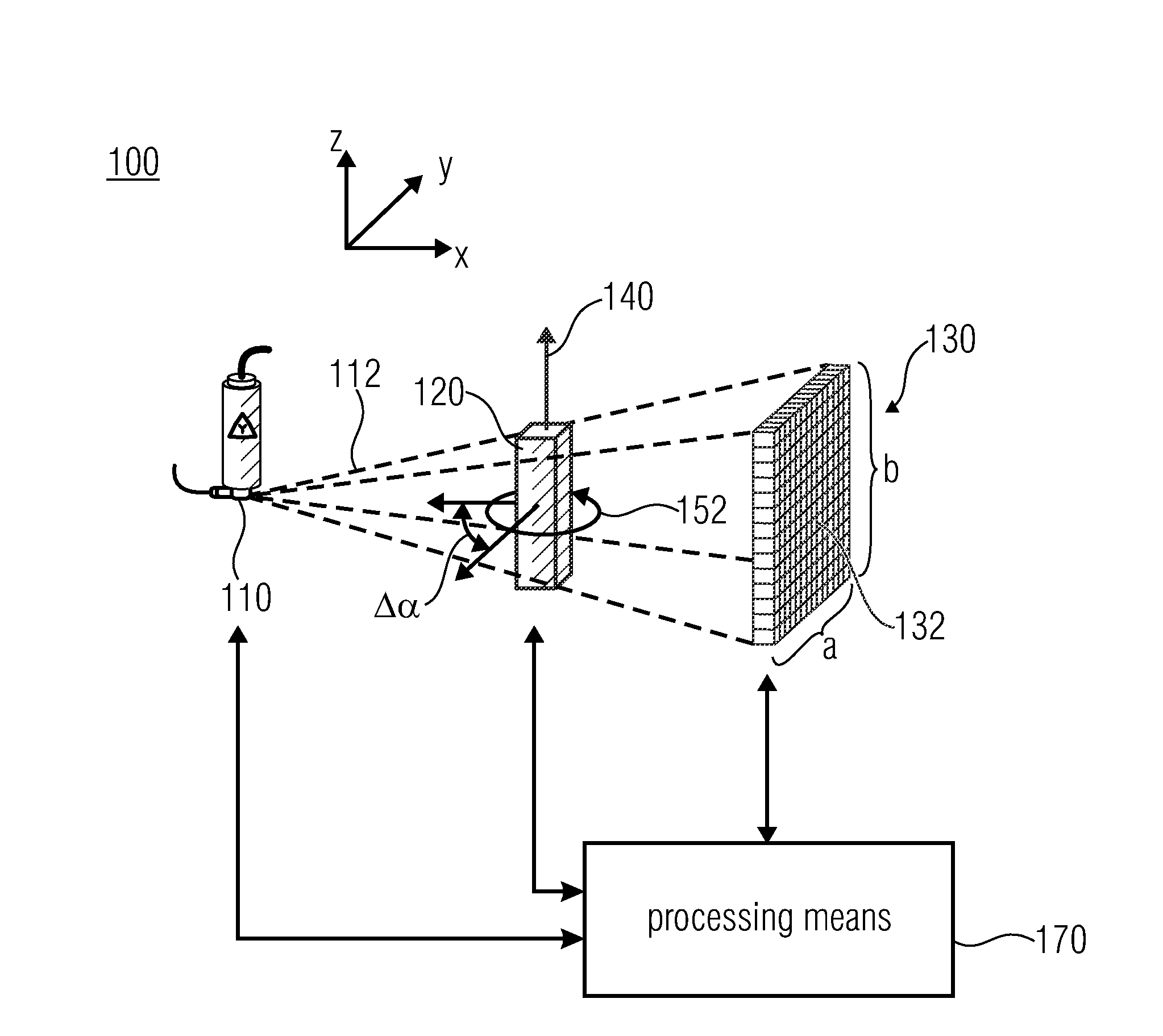
[0043]FIG. 1 shows an illustration of a CT system 100 according to one embodiment of the present invention for data determination for a computer tomography recording of a test object 120 (test body) (which is as interference-free or interference-reduced as possible). The CT system 100 for example comprises an x-ray tube 110 and a (planar) detector 130 sensitive for x-radiation 112 in the form of a flat screen detector or planar x-ray detector. The x-radiation 112 emitted by the x-ray source 110 penetrates or passes through the test object 120 and impinges...


PUM


Abstract

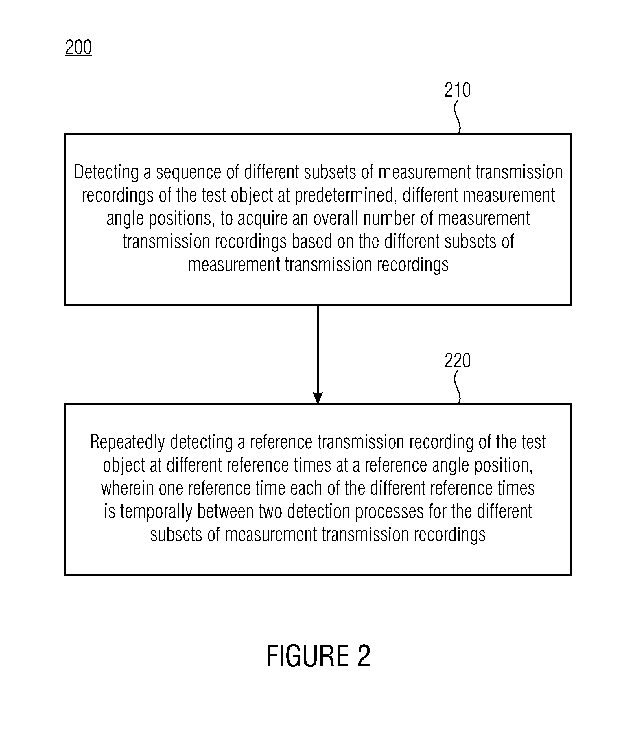
A method for data determination for a computer tomography recording of a test object includes detecting a sequence of different subsets of measurement transmission recordings of the test object at predetermined, different measurement angle positions, to acquire an overall number of measurement transmission recordings based on the different subsets of measurement transmission recordings; and a repeated detection of a reference transmission recording of the test object at different reference times at a reference angle position, wherein one reference time each of the different reference times is temporally between two detection processes for the different subsets of measurement transmission recordings.

Description

CROSS-REFERENCE TO RELATED APPLICATIONS[0001]This application claims priority from German Patent Application No. 102012205225.9, which was filed on Mar. 30, 2012, and is incorporated herein in its entirety by reference.BACKGROUND OF THE INVENTION[0002]The present invention relates to a computer tomography system and a method for data determination for a computer tomography recording of a test object or test body. In particular, the present invention relates to a device and a method for an operation-synchronized detection and compensation of time-dependent interferences at computer tomography systems.[0003]Computer tomography (CT) is widely used in the field of medicine and for example non-destructive materials testing. In computer tomography, the interaction between the generated x-radiation and the matter or material of the test object is detected.[0004]With conventional computer tomography systems, from an x-ray tube as a radiation source, x-rays in the form of a fan beam or a con...

Claims


Application Information

Patent Timeline
IPC IPC(8): G06T11/00
CPCA61B6/032A61B6/5205A61B6/547G01N2223/419G06T11/005G01N23/046A61B6/582
Inventor SCHMITT, MICHAELREISINGER, STEFANVOLAND, VIRGINIASALAMON, MICHAELKRUMM, MICHAEL
Owner FRAUNHOFER GESELLSCHAFT ZUR FOERDERUNG DER ANGEWANDTEN FORSCHUNG EV
Learn More