Drive control apparatus and drive control method for display panel

Inactive Publication Date: 2005-01-06
CANON KK
View PDF8 Cites 12 Cited by
  • Summary
  • Abstract
  • Description
  • Claims
  • Application Information

AI Technical Summary

Benefits of technology

Because according to the present invention, the modulation clock for the pulse width modulation is frequency-modulated while maintaining a high image quality, the unnecessary radiation from the display panel can be reduced. Therefore, members having a high electric conductivity, which is necessary conventionally for reducing the unnecessary radiation and do

Problems solved by technology

However, it has been found that even if the phase of data transfer clock is changed over, some kind of unnecessary radiation critical for the EMI, which is emitted from the display panel, cannot be suppressed.
However, the member having a high electric conductivity which does not sacrifice the optical characteristic is expensive.
However, in case where the screen siz

Method used


Image

  • Drive control apparatus and drive control method for display panel
  • Drive control apparatus and drive control method for display panel
  • Drive control apparatus and drive control method for display panel

Examples


first embodiment

(Composition)

First, the basic operation about the drive method of the matrix panel of the first embodiment will be described.

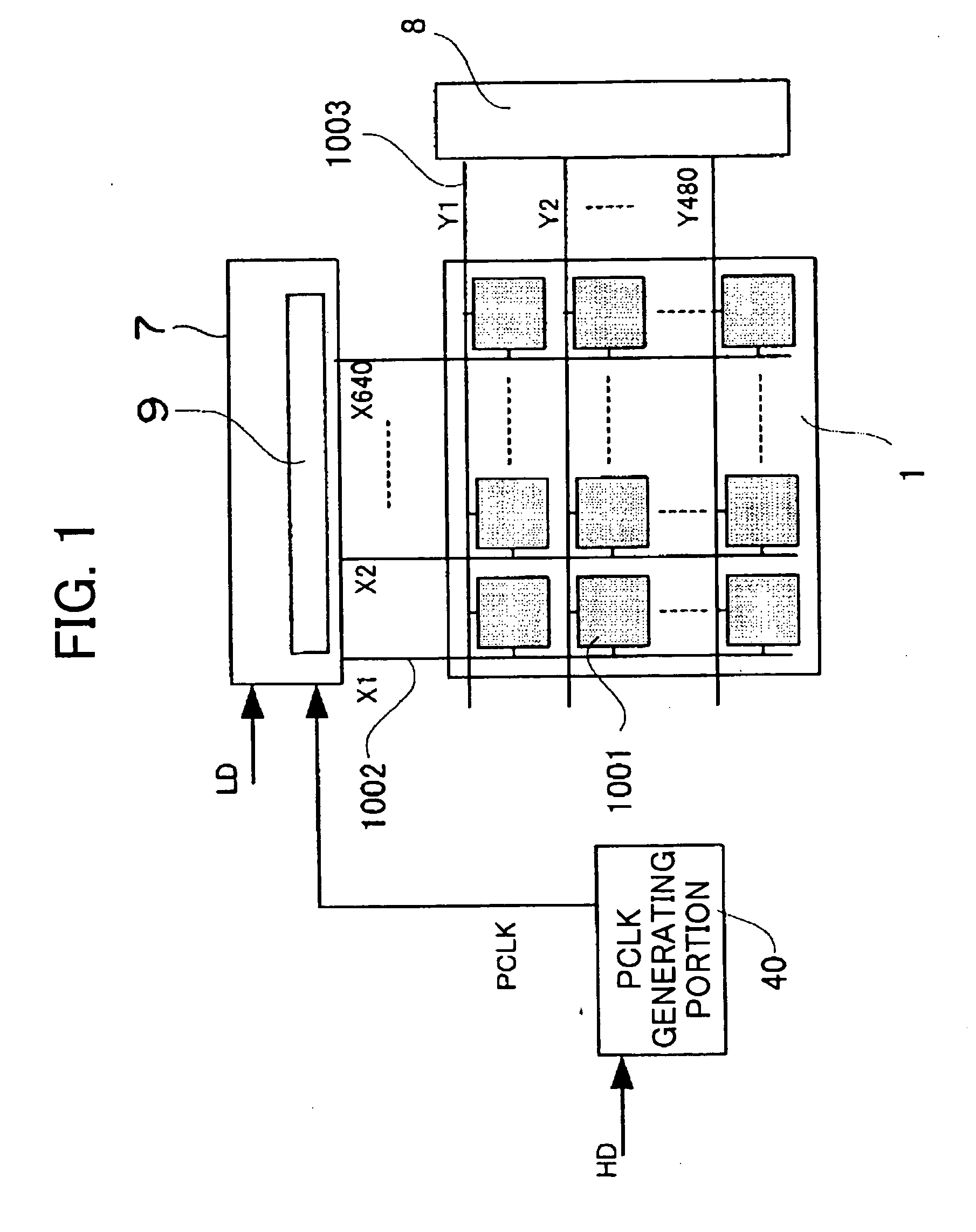
FIG. 1 shows a matrix panel having matrix wiring of 480 rows·640×3 (RGS) columns.

A pixel 1001 of a matrix panel (display panel) 1 is constructed containing a modulation device such as a cold cathode device and the modulation device is formed on a substrate like glass. In case of a display matrix panel using the cold cathode device, a substrate (not shown) like glass which is coated with fluorescent material and a high voltage is applied on is provided so as to oppose the pixel 1001 so that the fluorescent material emits light due to electrons emitted from the cold cathode device.

Reference numeral 1002 denotes column wiring (modulation wiring) and reference numeral 1003 denotes row wiring (scanning wiring). A physical intersection between the column wiring 1002 and the row wiring 1003 is insulated and a cold cathode device constituting the pixel 1001 is...

second embodiment

Next, the second embodiment will be described.

According to the first embodiment, the condition about the frequency modulation of the modulation clock (PCLK) is indicated about the difference in luminance between adjacent rows, which is a problem in subjective evaluation. An object of the second embodiment is to reproduce the luminance data and gradation characteristic of luminance faithfully. Because the structure of the image display unit and the operation of the unnecessary radiation of the second embodiment are equal to the first embodiment, a description thereof is omitted.

(Tolerable Condition of Image Quality)

According to the second embodiment of the present invention, the modulation clock (PCLK) is obtained by frequency-modulating the source clock at random like the first embodiment. That is, according to this example, the cycle of the PCLK is selected at random to reduce the level of its harmonics and its frequency is changed.

FIG. 7a shows a source clock and a modulat...

third embodiment

Next, the third embodiment of the present invention will be described.

In the first embodiment and second embodiment, the condition for the frequency modulation of the modulation clock (PCLK) about a difference in luminance between adjacent rows or relative to the luminance of the source clock, which is a problem in subjective evaluation, is indicated. According to the third embodiment, the aforementioned difference in display luminance is not set below a common tolerable value but below a tolerable value which is different depending on each gradation level on all gradation levels such as n=1, 2, 3, . . . 255 except 0 in order to obtain a further excellent image quality. Because the structure of the image display unit and the unnecessary radiation reduction method are the same as the first embodiment, description thereof is omitted.

(Tolerable Condition of Image Quality)

A case where a gamma compensated image signal (a signal raised to the 0.45 power preliminarily) is quantized ...


PUM


Abstract

A modulation clock supplied to a drive circuit (7) of a display panel (1) is frequency-modulated so as to spread its harmonics spectrum. The frequency deviation is so restricted that, if at least two pixels corresponding to two adjacent scanning wirings are displayed based on arbitrary same luminance data, a difference in display luminance in a specified period between one pixel and the other pixel is less than or equal to a tolerable value determined by the luminance data. Consequently, reduction in unnecessary radiation can be achieved at a lower cost while suppressing deterioration in image quality

Description

BACKGROUND OF THE INVENTION 1. Field of the Invention The present invention relates to a drive control apparatus and drive control method for a display panel for displaying an image signal outputted from a computer, TV image signal or the like. 2. Description of the Related Art Conventionally, as a method for reducing electromagnetic interference (EMI), for example, patent document 1 (Japanese Patent Application Laid-Open (JP-A) No. 8-320665), patent document 2 (JP-A No. 9-98152), patent document 3 (JP-A No. 9-232944) and patent document 4 (JP-A No. 9-289527) have been proposed. According to the above-mentioned conventional EMI reduction method, a system clock is frequency-modulated so as to spread the spectrum of harmonics of the system clock thereby to reduce EMI spectrum amplitude which is measured in a relatively wide band. According to the patent document 1, when digital data is transferred to a flat panel display, the phase of the data and its data transfer clock is chan...

Claims


Application Information

Patent Timeline
IPC IPC(8): G09G3/20H04N5/66G09G3/22
CPCG09G3/2014G09G3/2081G09G3/22G09G2330/06G09G2310/0275G09G2320/0276G09G2310/0224F21V33/0028F21W2121/00
Inventor ABE, NAOTOSAGANO, OSAMU
Owner CANON KK
Why Eureka
Try Eureka