Machine-tool or production machine with head-up display

a technology of head-up display and production machine, which is applied in the field of production machine, can solve the problems of not providing additional information that may be useful to an operator, and achieve the effects of reducing space requirements, reducing the number of components, and implementing cost-effectively

Active Publication Date: 2005-01-06
SIEMENS AG
View PDF12 Cites 32 Cited by
  • Summary
  • Abstract
  • Description
  • Claims
  • Application Information

AI Technical Summary

Benefits of technology

[0011] By integrating a head-up display with existing machine components, a display unit or a control panel can essentially “melt together” with the machine. A display or control panel can be implemented cost-effectively due to the reduced space requirement and the reduced number of components. The superposition of operator information in the machine space by the head-up display represents a fundamental innovation for machine startup, production processes, diagnostics and service. For example, faults in the manufacturing and production process can be directly indicated and superimposed at the location where they occurred. In addition, operating instructions can be visualized directly on the machine either step-by-step or separately for each process step which makes their evaluation much easier than with a disconnected, abstract representation on a conventional display screen.
[0012] The head-up display, unlike the afore-described conventional display units or control panels, can also withstand much better harsher environmental conditions typically found in a manufacturing environment.
[0014] According to another advantageous embodiment of the invention, the data and commands can be recorded by a camera or a touch-sensitive screen disposed on or integrated with the window. This allows a reliable acquisition of data and commands.

Problems solved by technology

These transparent windows enable an operator to monitor the manufacturing and production processes, but do not provide additional information that may be useful to an operator.

Method used


Image

  • Machine-tool or production machine with head-up display
  • Machine-tool or production machine with head-up display
  • Machine-tool or production machine with head-up display

Examples


Embodiment Construction

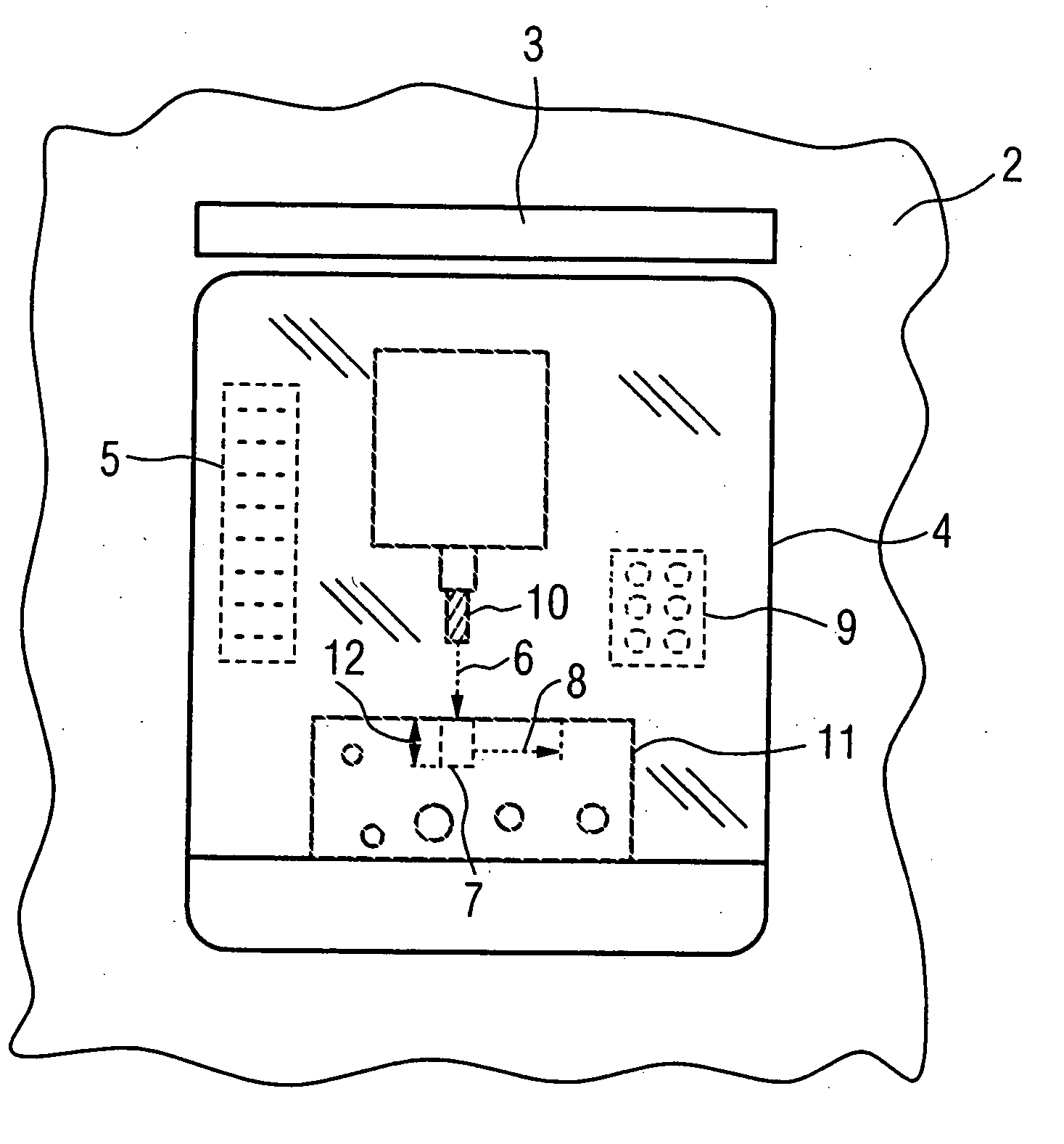
[0021] Throughout all the Figures, same or corresponding elements are generally indicated by same reference numerals. These depicted embodiments are to be understood as illustrative of the invention and not as limiting in any way. It should also be understood that the drawings are not necessarily to scale and that the embodiments are sometimes illustrated by graphic symbols, phantom lines, diagrammatic representations and fragmentary views. In certain instances, details which are not necessary for an understanding of the present invention or which render other details difficult to perceive may have been omitted.

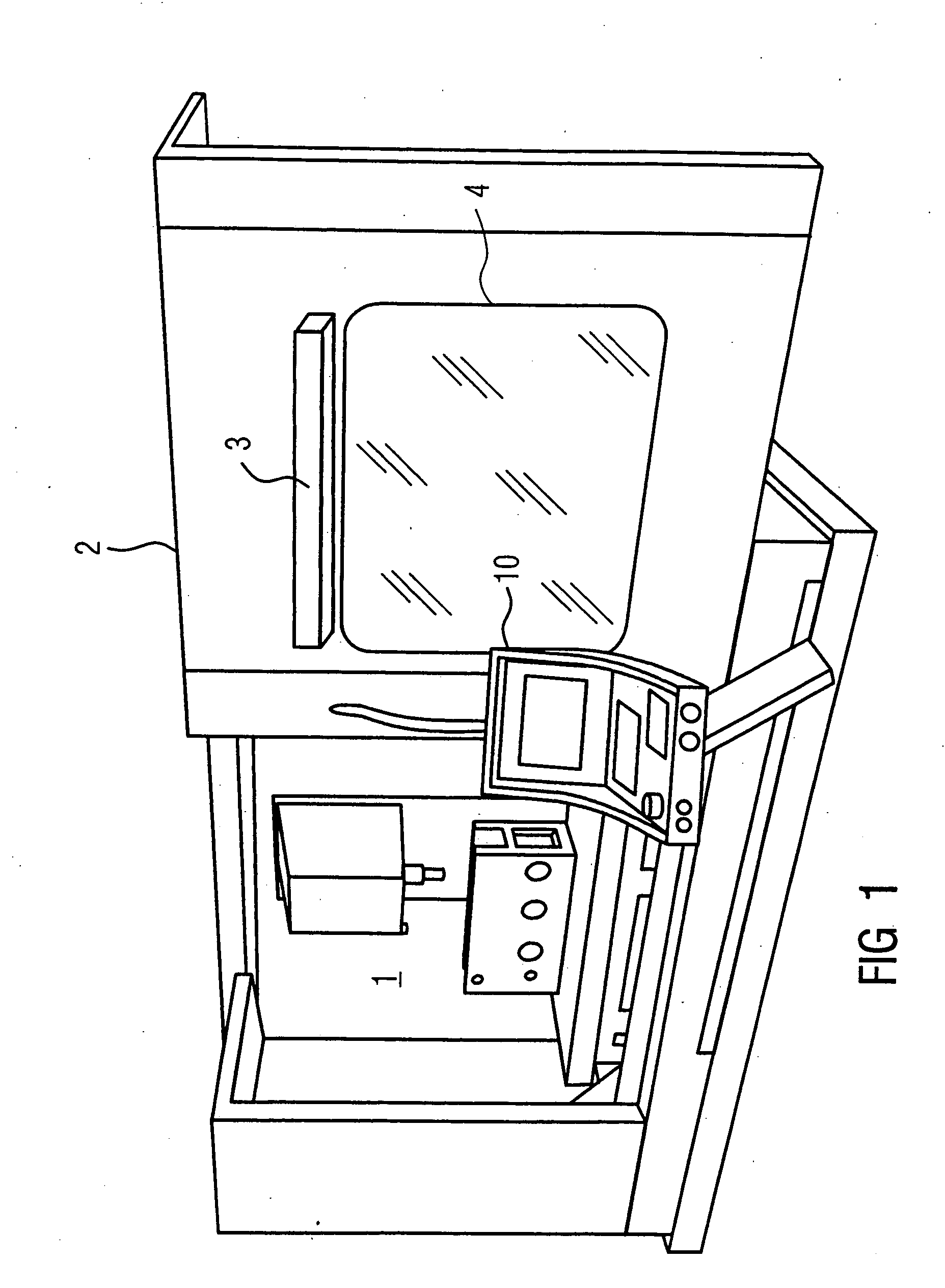
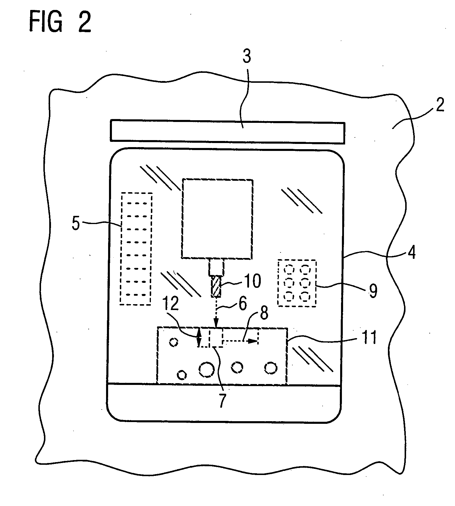
[0022] Turning now to the drawing, and in particular to FIG. 1, there is shown one embodiment of a machine-tool according to the present invention. The workspace 1 of the machine, where the actual manufacturing and production process takes place, is separated from the operator of the machine by a sliding door 2 which can be closed. FIG. 1 shows the machine with the sliding d...


PUM

PropertyMeasurementUnit
transparentaaaaaaaaaa
sizeaaaaaaaaaa
flexibilityaaaaaaaaaa

Abstract

A machine-tool production machine is disclosed, with a workspace that can be viewed by an operator through a window or transparent pane, whereby the window or transparent pane can be used with a projection unit as a head-up display for displaying information for the operator. The device provides the operator with a simple, cost-effective and clear representation of information about the manufacturing and production processes as well as other processes running on the machine.

Description

CROSS-REFERENCES TO RELATED APPLICATIONS [0001] This application claims the priority of German Patent Application, Serial No. 103 25 895.7, filed Jun. 6, 2003, pursuant to 35 U.S.C. 119(a)-(d), the disclosure of which is incorporated herein by reference. BACKGROUND OF THE INVENTION [0002] The present invention relates to a machine-tool or production machine, and more particularly to a machine with a workspace that can be viewed by an operator through a transparent window. [0003] Most commercially available modern machine-tools or production machines include a display unit and / or a control panel that can be used on location to parameterize, control and monitor a manufacturing or production process. The display unit typically includes a cathode ray tube or an LCD display, which is generally located on the side or the front of the machine and can be an integral component of a control panel. The display unit can also be mounted on a movable boom. [0004] Another type of display unit know...

Claims


Application Information

Patent Timeline
Patent Type & Authority Applications(United States)
IPC IPC(8): B23Q11/08B23Q17/24
CPCB23Q11/08B23Q11/0891Y10T409/309576G05B2219/32014Y10T409/30392B23Q17/24
Inventor DIRNFELDNER, RAINER
Owner SIEMENS AG
Why Eureka
Try Eureka