
Power factor correction method and apparatus and power supply using the same

Inactive Publication Date: 2005-01-06
SAMSUNG ELECTRONICS CO LTD
View PDF11 Cites 22 Cited by
  • Summary
  • Abstract
  • Description
  • Claims
  • Application Information

AI Technical Summary

Benefits of technology

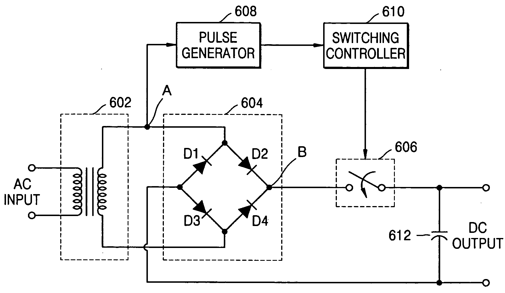
[0018] In order to solve the foregoing and / or other problems, it is an aspect of the present general inventive concept to provide a power factor correction method of correcting a power factor in a power supply which rectifies an input alternating-current (AC) voltage and smoothes the same using a capacitive input type smoothing circuit in order to supply a direct-current (DC) voltage the power factor correction method including providing the rectified voltage to a smoothing circuit in synchronization with the input AC voltage in a switching manner, so that power factor correction and characteristics of harmonics are enhanced.
[0021] The foregoing and / or other aspects of the present general inventive concept may be achieved by providing a power factor correction apparatus to correct a power factor in a power supply which smoothes an input alternating-current (AC) voltage via a capacitive input type smoothing circuit and stabilizes the smoothed direct-current (DC) voltage via a linear regulator, the power factor correction apparatus providing the rectified voltage to a smoothing circuit in a switching manner, so that power factor correction and characteristics of harmonics are enhanced.

Problems solved by technology

In addition, power factor correction and harmonics reduction become important issues in developing the power supply.
Accordingly, devices which generate current of harmonics more than a restricted value recommended by an importing country cannot be exported to the importing country.
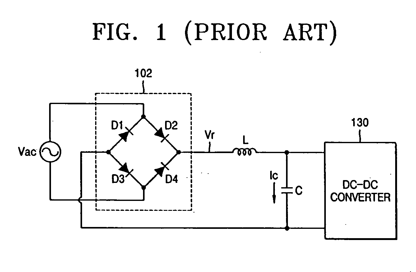
However, as the capacity of the capacitor becomes larger, a pulse-shaped large current is required to flow in order to store a large amount of energy in the capacitor in a short period of time.
Accordingly, the inductor used in a power factor correction device becomes large in shape and weight and high in price.

Method used


Image

  • Power factor correction method and apparatus and power supply using the same
  • Power factor correction method and apparatus and power supply using the same
  • Power factor correction method and apparatus and power supply using the same

Examples


Embodiment Construction

[0037] Reference will now be made in detail to the embodiments of the present general inventive concept, examples of which are illustrated in the accompanying drawings, wherein like reference numerals refer to the like elements throughout. The embodiments are described below in order to explain the present general inventive concept by referring to the figures.

[0038]FIG. 4 is a flowchart showing a power factor correction method according to an embodiment of the present general inventive concept.

[0039] The power factor correction method shown in FIG. 4 may include a rectification process S402, a cut-off process S404, and a smoothing process S406.

[0040] In the rectification process S402, an alternating-current (AC) voltage provided from an AC voltage transformer can be rectified. The rectification process S402 can be performed by a conventional bridge rectifier, such as a rectifier 302 of FIG. 3.

[0041] Meanwhile, when the AC voltage is transformed via an AC voltage transformer, a l...


PUM


Abstract

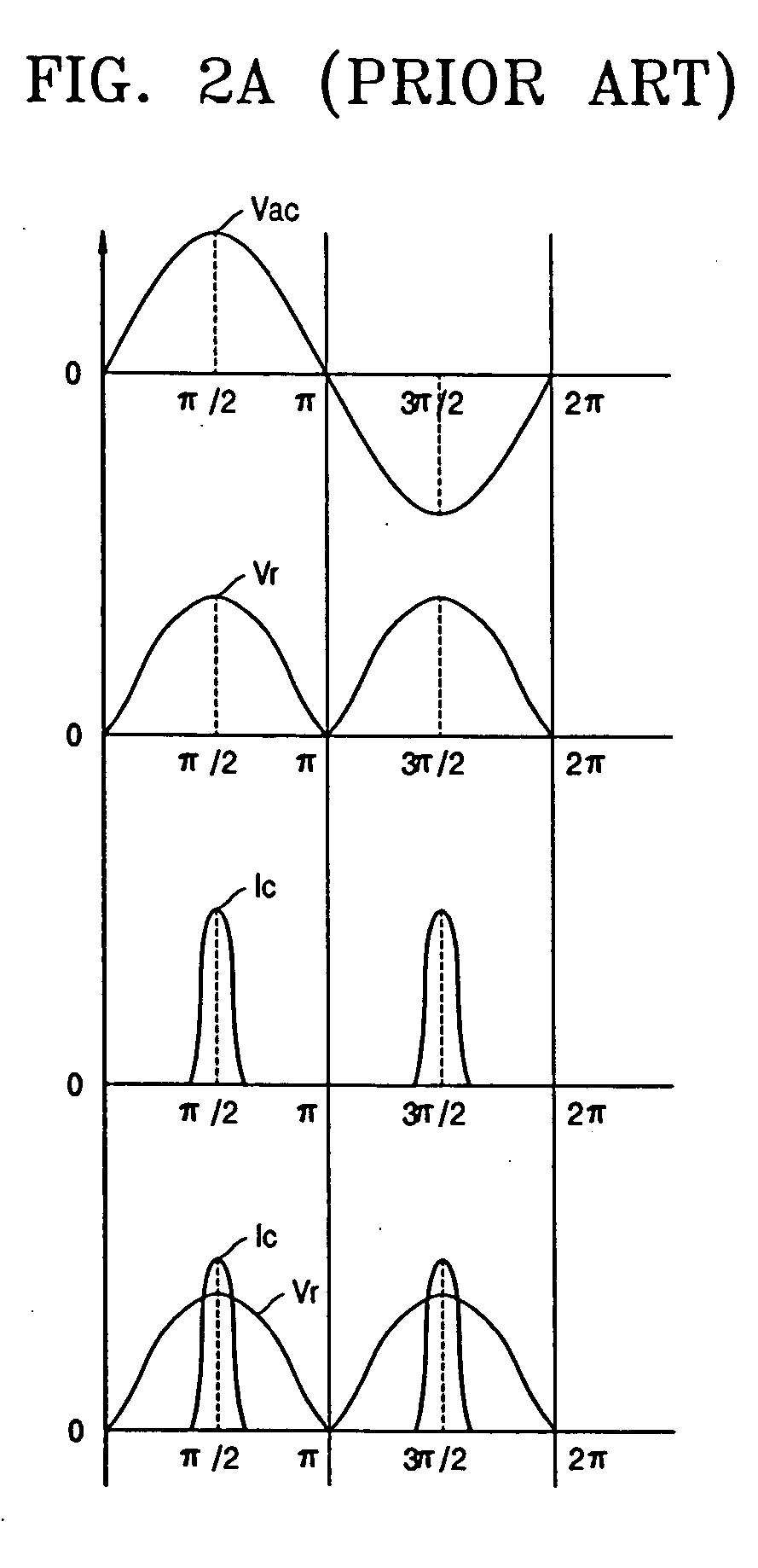
A power factor compensation method and apparatus adapted for use in a power supply which provides direct-current (DC) power via a capacitive input type smoothing circuit, and an improved power supply using the same. The power factor compensation method can correct a power factor in the power supply which rectifies an input alternating-current (AC) voltage and smoothes the same using the capacitive input type smoothing circuit to supply a DC voltage. The method may include rectifying the input AC voltage, cutting off a pulsating current generated in the rectifying operation at phases of about π / 2 and 3 π / 2 of the input AC voltage so that the pulsating current is not transferred to a smoothing circuit, and smoothing the pulsating current generated in the cutting-off operation. The power factor compensation apparatus does not form a peak envelope of current at phases of about π / 2 and 3 π / 2 of the input AC voltage, thereby improving a power factor and reducing a harmonic current. The power factor compensation apparatus uses a leak inductance in an AC transformer at maximum to provide a low-price power supply.

Description

CROSS-REFERENCE TO RELATED APPLICATIONS [0001] This application claims the priority of Korean Patent Application No. 2003-44341, filed on Jul. 1, 2003, in the Korean Intellectual Property Office, the disclosure of which is incorporated herein in its entirety by reference. BACKGROUND OF THE INVENTION [0002] 1. Field of the Invention [0003] The present general inventive concept relates to power factor correction, and more particularly, to a power factor correction method and apparatus adapted for used in a power supply which provides a direct-current (DC) power using a capacitive input type smoothing circuit, and an improved power supply using the same. [0004] 2. Description of the Related Art [0005] Recently, power supplies which can be stable, compact and light have been developed to be applied to factory automation devices, office automation devices, communications devices, and power systems. In addition, power factor correction and harmonics reduction become important issues in de...

Claims


Application Information

Patent Timeline
IPC IPC(8): H02M1/00H02M1/14H02M1/42H02M3/335
CPCY02B70/126H02M1/4208Y02B70/10Y02P80/10H02M1/14
Inventor LEE, JIN-HYUNGLEE, KYOUNG-GEUN
Owner SAMSUNG ELECTRONICS CO LTD
Learn More