Mixing bag or vessel having a receiver for a fluid-agitating element

a technology of fluid agitation and fluid-agitation element, which is applied in the field of vessels, can solve the problems of contamination or leakage of fluid-agitation elements during mixing, environmental contamination dangers, and degradation of products, and achieve the effect of convenient alignment of fluid-agitation elements

Active Publication Date: 2005-01-06
PALL TECH UK
View PDF99 Cites 114 Cited by
  • Summary
  • Abstract
  • Description
  • Claims
  • Application Information

AI Technical Summary

Benefits of technology

[0012] The bag may further include a second receiver projecting outwardly from the bag. The second receiver facilitates aligning the fluid-agitating element with an external structure, such as a motive device for levitating or rotating t

Problems solved by technology

One significant limitation or shortcoming of such an arrangement is the danger of contamination or leakage during mixing.
This opening provides an opportunity for bacteria or other contaminants to enter, which of course can lead to the degradation of the product.
A corresponding danger of environmental contamination exists in applications involving hazardous or toxic fluids, or suspensions of pathogenic organisms, since dynamic seals or bearings are prone to leakage.
Cleanup and sterilization are also made difficult by the dynamic bearings or seals, since these structures typically include folds and crevices that are difficult to reach.
Despite the advantages of this type of mixing systems and others where the need for a shaft penetrating into the vessel or dynamic seal is eliminated, a substantial, but heretofore unsolved problem with such systems is the difficulty in coupling a fluid-agitating element with an external motive device providing the rotation and/or levitation force.
However, this is considered inconvenient and time consuming, especially if fluid is already present in the bag.
Moreover, in the case where the bag is relatively large (e.g., capable of holding 100 liters or more) or formed of an opaque material (e.g., black), achieving the proper positioning of the fluid-agitati

Method used


Image

  • Mixing bag or vessel having a receiver for a fluid-agitating element
  • Mixing bag or vessel having a receiver for a fluid-agitating element
  • Mixing bag or vessel having a receiver for a fluid-agitating element

Examples


Embodiment Construction

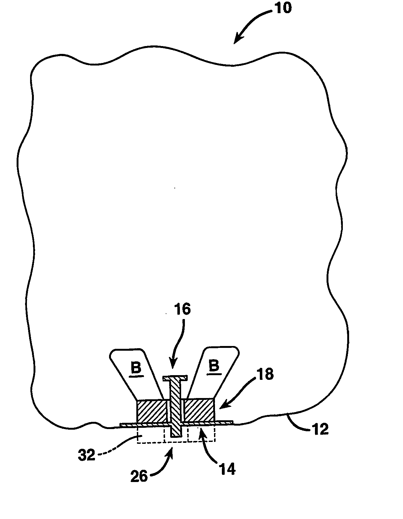
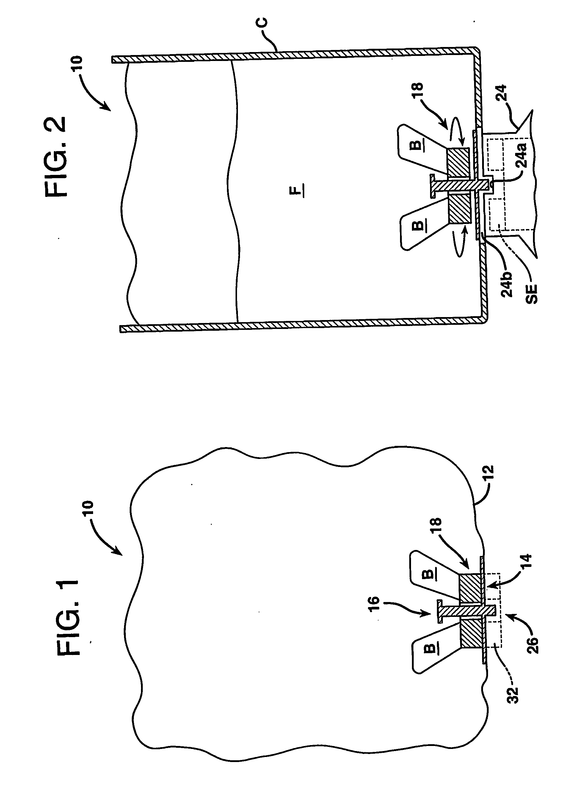
[0048] Reference is now made to FIG. 1, which discloses one embodiment of the vessel of the present invention in the form of a bag 10. In this embodiment, the bag 10 includes a body having a flexible or non-rigid portion 12, which is illustrated schematically, and a rigid or stiff portion 14, which is shown in cross-section. However, as outlined further in the description that follows, the use of the many of the present inventive concepts disclosed herein with vessels that are completely rigid is also possible.

[0049] The bag 10 may be hermetically sealed and may have one or more openings or fittings (not shown) for introducing or recovering a fluid. Alternatively, the bag 10 may be unsealed or open-ended. The particular geometry of the bag 10 employed normally depends on the application and is not considered critical to the invention. For example, in the case of a sterile fluid, a hermetically sealed, pre-sterilized bag with an aseptic fitting might be desirable; whereas, in the ca...


PUM

PropertyMeasurementUnit
Flexibilityaaaaaaaaaa
Shapeaaaaaaaaaa
Magnetismaaaaaaaaaa

Abstract

A vessel in which a fluid is received and agitated using an internal fluidagitating element driven by an external motive device is disclosed. In one aspect, the vessel is a bag including a first receiver for receiving and holding a fluid-agitating element at a home location. The first receiver may be in the form of an inwardly projecting post having an oversized portion for capturing the fluid-agitating element, but various other forms are disclosed. Use of this feature in completely rigid vessels where the fluid-agitating element is free of direct attachment from a first receiver having an oversized portion is also disclosed. In another aspect, the vessel or bag further includes a second receiver for receiving a portion of an external structure, such as a motive device, and aligning the vessel relative thereto. Related methods are also disclosed.

Description

[0001] This application claims the benefit of U.S. Provisional Patent Application Ser. No. 60 / 326,833, filed Oct. 3, 2001, the disclosure of which is incorporated herein by reference.TECHNICAL FIELD [0002] The present invention relates generally to vessels in which fluids are agitated and, more particularly, to a vessel or bag including at least one receiver for receiving and holding a fluid-agitating element at a home location. BACKGROUND OF THE INVENTION [0003] Most pharmaceutical solutions and suspensions manufactured on an industrial scale require highly controlled, thorough mixing to achieve a satisfactory yield and ensure a uniform distribution of ingredients in the final product. Agitator tanks are frequently used to complete the mixing process, but a better degree of mixing is normally achieved by using a mechanical stirrer or impeller (e.g., a set of mixing blades attached to a metal rod). Typically, the mechanical stirrer or impeller is simply lowered into the fluid throug...

Claims


Application Information

Patent Timeline
IPC IPC(8): B01FB01F27/906B65D33/00
CPCB01F1/0011B01F2215/0073B01F13/0818B01F13/0827B01F13/0845B01F13/0863B01F15/00071B01F15/00824B01F15/00831B01F15/00837B01F15/0085B01F2215/0032B01F2215/0034B01F2215/0036B01F2215/0037B01F7/162B01F21/10B01F27/808B01F33/4532B01F33/4534B01F33/452B01F33/453B01F35/146B01F35/511B01F35/513B01F35/50B01F35/51B01F2101/2202B01F2101/2204B01F2101/23B01F2101/22B01F2101/44
Inventor TERENTIEV, ALEXANDRE N.
Owner PALL TECH UK
Why Eureka
Try Eureka