Fan blade
- Summary
- Abstract
- Description
- Claims
- Application Information
AI Technical Summary
Benefits of technology
Problems solved by technology
Method used
Image
Examples
first example
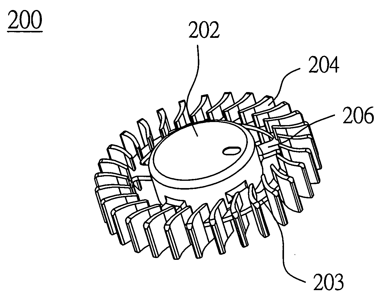
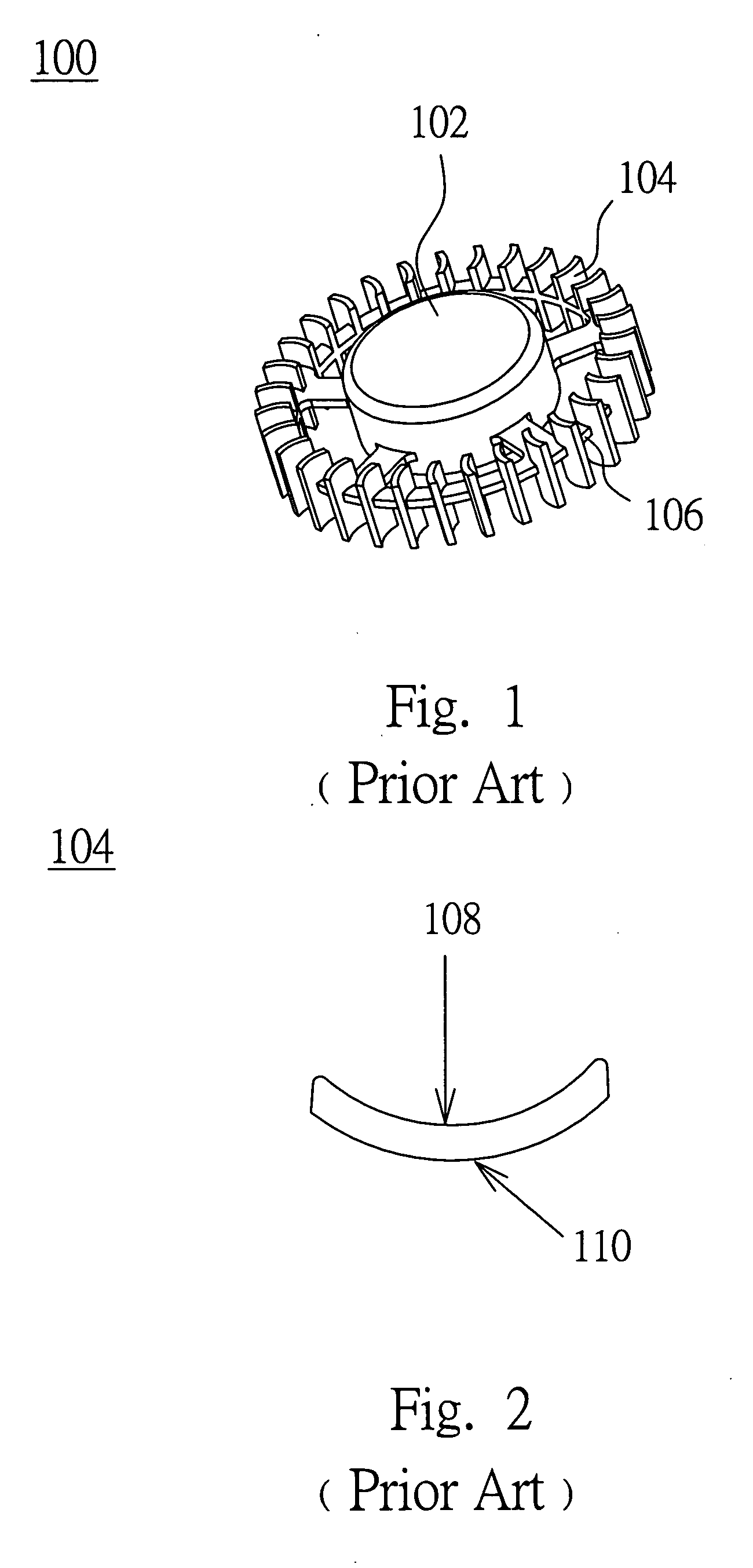
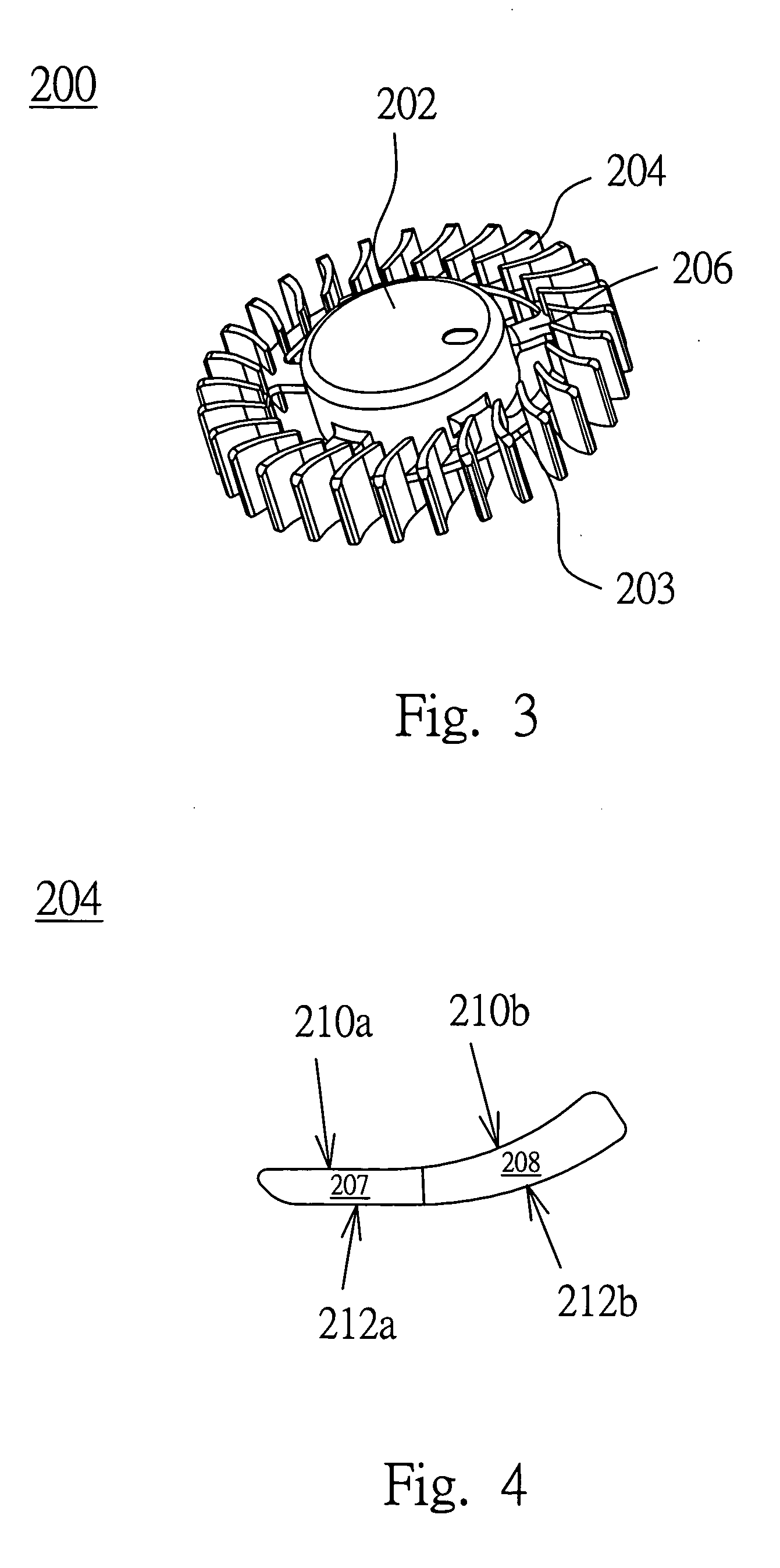
[0025] Referring to FIG. 3 to FIG. 5, FIG. 3 is a schematic diagram illustrating an impeller according to the first example in the preferred embodiment of the present invention, FIG. 4 is a front view of a fan blade 204; and FIG. 5 is a front view of the impeller 200. The impeller 200 has a hub 202, an annular part 203, fan blades 204, and a connection portion 206. The fan blades 204 are connected to the hub 202 via the connection portion 206, such as a rib.
[0026] The hub 202 includes a motor module used for driving the hub 202 to perform the motion of rotation. The annular part 203 surrounds the hub 202 and the annular part 203 is for disposing the fan blade 204 thereon. The connection portion 206 disposed between the annular part 203 and the hub 202 and the shape of the connection portion 206 can be such as a column shape, a radiation shape, an arc shape, the shape used in an axial-flow fan blade or a streamline shape, etc.
[0027] Each of the fan blades 204 is connected to the an...
second example
[0031] Further, referring to FIG. 6, it is a schematic diagram illustrating an impeller 300 according to the second example in the preferred embodiment of the present invention. The difference between the impeller 300 and the aforementioned impeller 200 is that each of the fan blades 304 of the impeller 300 has a larger windward area than each of the fan blades 204 of the impeller 200. In this case, the end of each fan blade 304 on an annular part 303 can be at the location closer to the hub 302, so that greater air pressure, air flow and the better visual effect are obtained when the impeller 300 is applied to a centrifugal fan or a blower.
third example
[0032] Referring to FIG. 7, it is a schematic diagram illustrating an impeller 400 according to the third example in the preferred embodiment of the present invention. The difference between the impeller 400 and the aforementioned impeller 200 is that the impeller 400 further includes a base 406 located around the hub 402 and horizontally extended from the hub 402, and each of the fan blades 404 of the impeller 400 is vertically extended from the base 406 and on the base 406, or the fan blades 404 can be both vertically extended from the base 406 toward up and down, and the base 406 is considered as horizontally being in the middle of each fan blade 404. As to this type of impeller 400, the hub 402, the base 406 and the fan blades 404 can be integrally formed so as to reduce the process steps and thus shortening process time.
PUM
 Abstract
Description
Claims
Application Information
 - R&D
- Intellectual Property
- Life Sciences
- Materials
- Tech Scout
- Unparalleled Data Quality
- Higher Quality Content
- 60% Fewer Hallucinations
Browse by: Latest US Patents, China's latest patents, Technical Efficacy Thesaurus, Application Domain, Technology Topic, Popular Technical Reports.
© 2025 PatSnap. All rights reserved.Legal|Privacy policy|Modern Slavery Act Transparency Statement|Sitemap|About US| Contact US: help@patsnap.com


