Solvent prewet and method to dispense the solvent prewet
Inactive Publication Date: 2005-01-06
CONVERSANT INTPROP MANAGEMENT INC
View PDF26 Cites 1 Cited by
Summary
Abstract
Description
Claims
Application Information
AI Technical Summary
This helps you quickly interpret patents by identifying the three key elements:
Problems solved by technology
Method used
Benefits of technology
Benefits of technology
[0017] In another embodiment, a slow-evaporation solvent is used. In one embodiment the solvent comprises a diacetone alcohol. With the use of solvents such as diacetone alcohol the vapor pressure is very low (which means the evaporation rate is very slow). This enables the process to use very little solvent prewet solution (0.3-1.0 cc per wafer) and achieve very good resist thickness profiles with only 0.5 cc of resist per wafer. The results are a very clean film, with good uniformity (generally less than 50 angstroms on an eight-inch wafer) achieved with the use of significantly le
Problems solved by technology
The solvent and resin combination, however, directly affects the resist film's adhesion and etch resistance characteristics.
Both of these materials have a relatively high evaporation rate, which accelerates the drying process.
When one considers the volume of wafers processed over, for example, a years time, this is a significant amount of resist and a significant part of the cost of processing.
As a result, extending the time for the solvent to evaporate by using slower spin-ramp speeds contributes to thickness non-uniformity created by the drying and film setting-up tendencies of the solution.
High spin-ramp speed, however, contributes to higher maintenance costs resulting from excessive wear on the motor.
The trend in conventional processes is to modify the spin-ramp speed, compromising between coverage quality and the cost
Method used
Image
Click on the blue label to locate the original text in one second.
Reading with bidirectional positioning of images and text.
Examples
Embodiment Construction
[0024] In the following detailed description, reference is made to the accompanying drawings which form a part hereof, and in which is shown by way of illustration specific embodiments in which the invention may be practiced. These embodiments are described in sufficient detail to enable those skilled in the art to practice the invention, and it is to be understood that other embodiments may be utilized and that structural, logical and electrical changes may be made without departing from the spirit and scope of the present invention. The following detailed description is, therefore, not to be taken in a limiting sense, and the scope of the present invention is defined by the appended claims.
[0025] By way of definition, in the following text the term “wafer” is intended as a representative reference to the substrate or base upon which an integrated circuit device is to be constructed. The term “resist” or “photoresist” represents any of the set of materials known and used in the ar...
PUM
Abstract
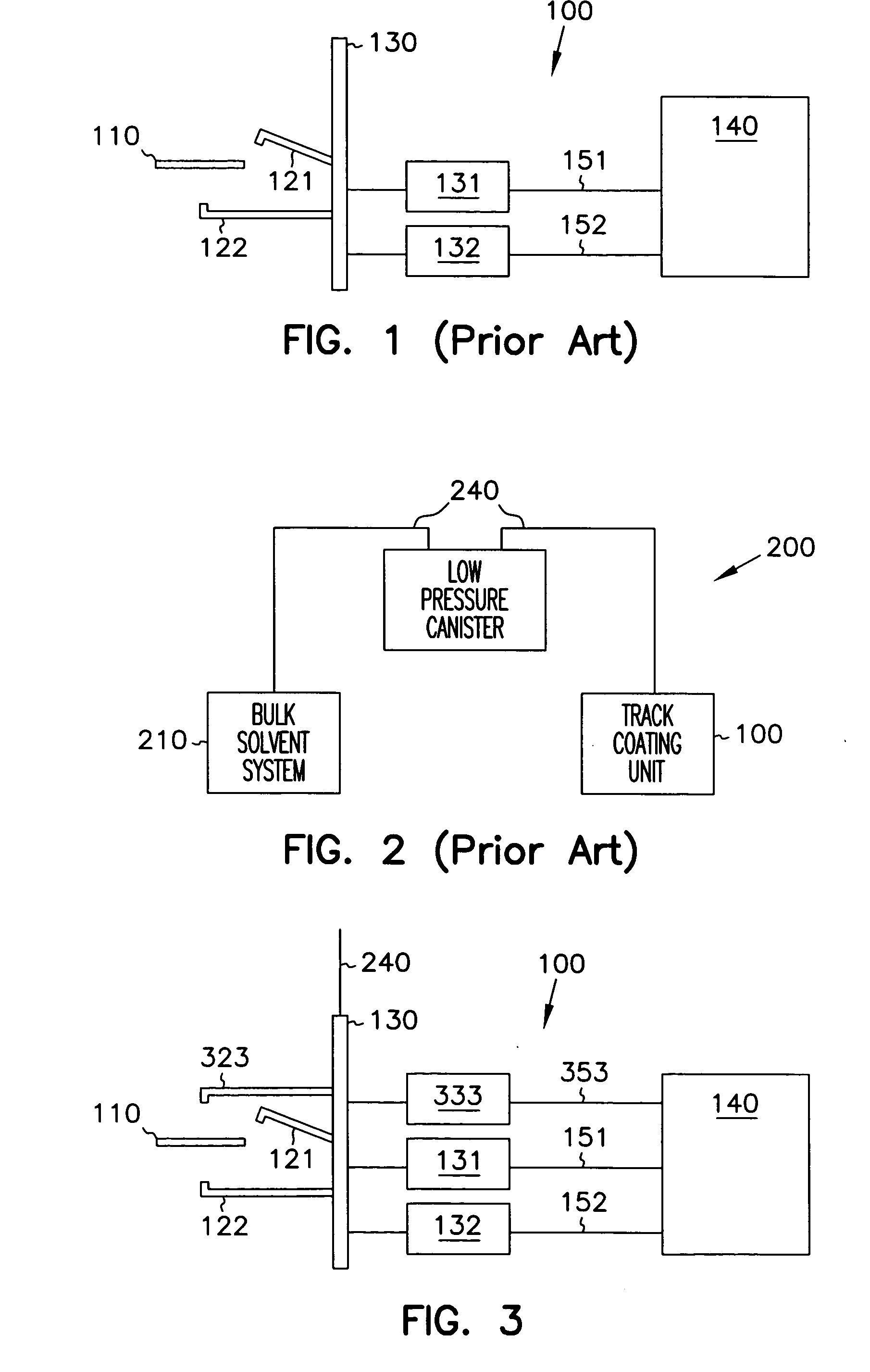
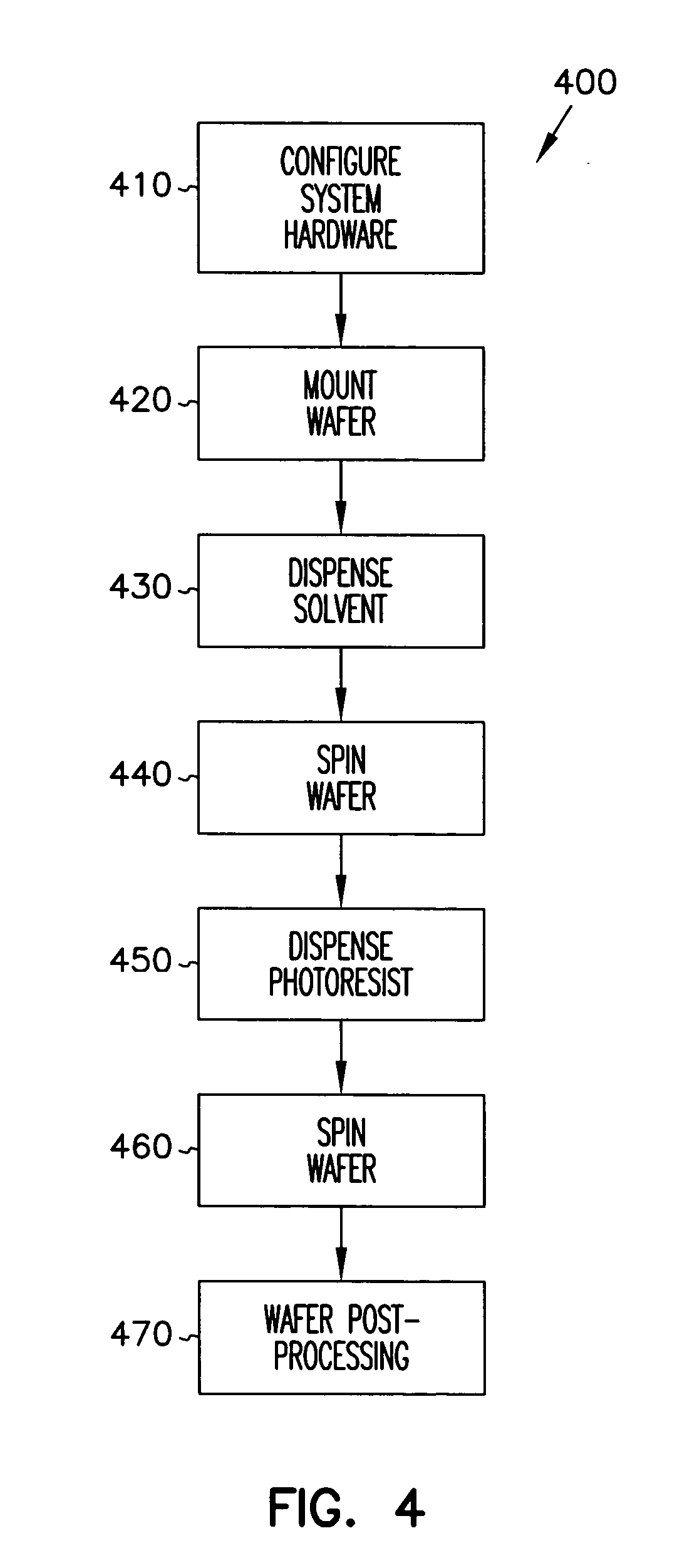
A method and apparatus is provided for more efficient application of photoresist to a wafer surface. One aspect of the method comprises applying solvent to the wafer and spinning it to coat the entire wafer surface prior to the application of photoresist. This reduces surface tension on the wafer and reduces the amount of resist required to achieve a high quality film. The apparatus comprises adding a third solenoid and nozzle to the coating unit to accommodate the application of solvent to the center of the wafer surface. The method also describes incorporating a new solvent comprising diacetone alcohol, which is a low-pressure solvent, providing extended process latitudes and reduced material expenditures.
Description
[0001] This application is a Continuation of U.S. application Ser. No. 09 / 941,476, filed Aug. 29, 2001, which is a Divisional of U.S. application Ser. No. 09 / 650,876, filed Aug. 30, 2000, now U.S. Pat. No. 6,284,676, which is a Continuation of U.S. application Ser. No. 08 / 974,015, filed Nov. 19, 1997, now U.S. Pat. No. 6,147,010, which is a File-Wrapper Continuation of U.S. application Ser. No. 08 / 749,001, filed Nov. 14, 1996, abandoned.FIELD OF THE INVENTION [0002] The present invention relates in general to processing semiconductor wafers, and particularly to preparing a semiconductor wafer before and after the application of resist. BACKGROUND OF THE INVENTION [0003] In the lithographic process, a photoresist is applied as a thin film to a substrate (for example, SiO2 on Si), and subsequently exposed through a mask or reticule. The mask contains clear and opaque features that define the pattern which is to be created in the photoresist layer. Areas in the photoresist exposed to l...
Claims
Application Information
Patent Timeline
Application Date:The date an application was filed.
Publication Date:The date a patent or application was officially published.
First Publication Date:The earliest publication date of a patent with the same application number.
Issue Date:Publication date of the patent grant document.
PCT Entry Date:The Entry date of PCT National Phase.
Estimated Expiry Date:The statutory expiry date of a patent right according to the Patent Law, and it is the longest term of protection that the patent right can achieve without the termination of the patent right due to other reasons(Term extension factor has been taken into account ).
Invalid Date:Actual expiry date is based on effective date or publication date of legal transaction data of invalid patent.

