7FAstage 1 abradable coatings and method for making same

a technology of abradable coatings and abradable coatings, which is applied in the direction of machines/engines, instruments, transportation and packaging, etc., can solve the problems of short lifespan of cbn at the anticipated high operating temperature and the complexity of the tipping process, so as to improve the overall engine performance, reduce the airflow, and minimize the effect of tip loss damag

a technology of abradable coatings and abradable coatings, which is applied in the direction of machines/engines, instruments, transportation and packaging, etc., can solve the problems of short lifespan of cbn at the anticipated high operating temperature and the complexity of the tipping process, so as to improve the overall engine performance, reduce the airflow, and minimize the effect of tip loss damag

US20050003172A1Inactive Publication Date: 2005-01-06GENERAL ELECTRIC CO

Image

  • 7FAstage 1 abradable coatings and method for making same
  • 7FAstage 1 abradable coatings and method for making same
  • 7FAstage 1 abradable coatings and method for making same

Examples


example 1

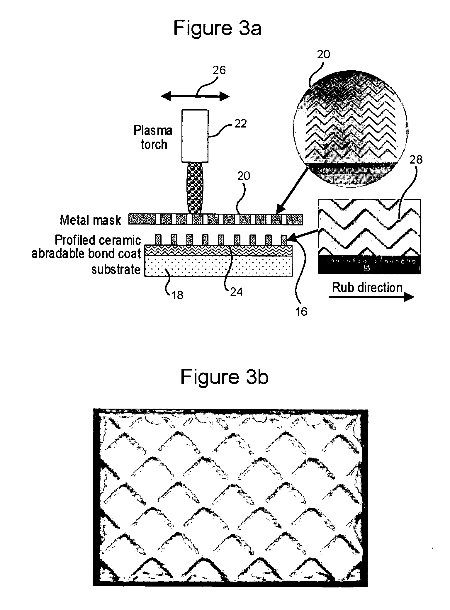
Profiled Ceramic Abradable Coating via Plasma Spraying through Masking (FIG. 3), Rub Tested at 1500F Temperature

[0061] In this example, a metal mask was fabricated by water-jet cutting a 90° chevron pattern (see FIG. 3) onto a ⅛″ thick steel plate. The width of groove was 0.05″ on the plasma gun side and 0.06″ on the substrate side. The spacing between the grooves was about 0.2.″ The substrate comprised a 5″×5″ IN718 plate which was grit-blasted with 60 mesh virgin Al2O3 grit at 60 psi air. A 0.006″ thick metallic bond coat of Praxair Ni211-2 (NiCrAlY) was applied onto the substrate followed by the application of 0.04″ thick profiled ceramic top coat of Sulzer Metco XPT395 (7% YSZ with 15 wt % polyester) through the metal mask (see FIG. 3).

[0062] Table 1 lists the plasma and spray parameters for the bond coat and the ceramic top coat.

TABLE 1Bond coatTop coatPLASMA SPRAY EQUIPMENTGUN MFR. / MODEL NO.:METCO 7 MBNOZZLE (ANODE NO.):GGELECTRODE (CATHODE NO.):7B63ARC GAS SETTINGSPRIMARY...

example 2

[0065] More samples were prepared with chevron (as described in 0027) as well as diamond patterns (as described in 0016). These samples (FIG. 6) were rub tested at 1050 ft / s tip velocity, where only one untipped cutting blade of GTD111 was used. The tests were conducted at 1700F temperature. Test data with these samples indicate, blade wear of 0-6% of the total incursion depth of 0.04″ which removed the ridges from the coatings in both types of patterns.

example 3

[0066] More samples were prepared with chevron patterns (as described in 0039) on previously TBC-coated Rene N5 samples. These samples were then thermal-cyclic tested in a high temperature air furnace at 2000° F. The test cycle was: ramp up to 2000F in 15 min., hold at 2000° F. for 45 min., and cool to room temperature in 10 min. FIG. 8 shows one of the samples after 1000 such cycles and there is no visual spallation of the abradable coating as well as the TBC. This test result indicates the compatibility of the patterned abradable coating to TBC in thermal cyclic performance.


PUM

PropertyMeasurementUnit
thickaaaaaaaaaa
thickaaaaaaaaaa
thicknessaaaaaaaaaa

Abstract

A method of applying a profiled abradable coating onto a substrate in which an abradable ceramic coating composition is applied to a metal substrate using one or more coating application techniques to produce a defined ceramic pattern without requiring a separate web or grid to be brazed onto the substrate. The invention is particularly designed to withstand the higher operating temperatures encountered with the stage 1 section of 7FA+e gas turbines to allow for increased coating life without significant deterioration in structural or functional integrity. Typically, the grid pattern coating begins approximately 0.431″ after the leading edge of the shroud, and ends approximately 1.60″ before the trailing edge of the shroud. In the case of diamond-shaped patterns, the grid pattern will be about 0.28″ long and 0.28″ wide, with an overall thickness of about 0.46.″ The coatings thus provide the required levels of abradability and leakage performance and may be applied as a chevron or diamond pattern with the shape oriented such that the diagonals run perpendicular and parallel to the sides of the shroud.

Description

[0001] This application is a continuation-in-part of commonly-owned application Ser. No. 10 / 320,480, filed Dec. 17, 2002, the entire disclosure of which is hereby incorporated by reference.[0002] The present invention relates to high temperature abradable coatings and to the method for making such coatings. Specifically, the invention, provides patterned high temperature abradable coatings, i.e., coatings having defined patterns for use on stage 1 shrouds without bucket tipping. Normally, in order to abrade high temperature abradable coatings, particularly ceramic abradables, reinforcing the bucket tip with a material having high strength characteristics at elevated temperatures is a necessity. In such cases, materials such as cubic Boron Nitride, silicon carbide or like materials are often used either in the form of entrapped coarse grits or a fine coating applied by a process such as, for example, thermal spray process, direct-write technology, PVD or CVD. BACKGROUND OF THE INVENT...

Claims


Application Information

Patent Timeline
06 Jan 2005
Publication
US20050003172A1
IPC
C23C4/10; C23C4/11
CPC
C23C4/005; C23C4/04; C23C4/18; C23C4/185; F01D11/122; C23C4/02; Y10T428/12611; C23C4/127
Inventors
WHEELER, JAMES DONALD; GHASRIPOOR, FARSHAD