Multiband receiver and method associated therewith

a multi-band receiver and receiver technology, applied in the field of multi-band receivers, can solve the problems of large difficulty in implementation of transmission standards, and achieve the effect of improving reception quality

Inactive Publication Date: 2005-01-06
GIGASET COMMUNICATIONS
View PDF12 Cites 14 Cited by
  • Summary
  • Abstract
  • Description
  • Claims
  • Application Information

AI Technical Summary

Benefits of technology

[0009] According to the present invention, the use of an RF / IF converter for conversion of the RF signals to a large number of intermediate frequency signals, with a large number (which corresponds to the large number of RF signals) of local oscillators being used to produce in-phase and quadrature components associated with the carrier frequencies, as well as the use of an in-phase and quadrature mixer for mixing the respective in-phase and quadrature components with the RF signals in order to produce IF in-phase and IF quadrature components in an intermediate frequency band, allow the intermediate frequency signals which are desired for further processing to be filtered out in a simple and very accurate manner using an additional complex filter, on the basis of the intermediate frequency signals. Thus, not only is it possible to use a single radio receiver for a large number of multiband radio frequencies or RF signals at the same time, but this also results in an extremely flexible configuration for implementation of transmission standards which have not yet been agreed or have so far been agreed only with a very great degree of difficulty.
[0010] The intermediate frequency signals preferably have unreflected and mirror-image signals in a low intermediate frequency band (low IF), with the complex filter producing a phase shift between the associated in-phase and quadrature components of these signals such that the undesirable mirror-image signal components are at least partially canceled out. The use of signals in a low intermediate frequency band allows the provision of particularly low-cost multiband receivers. The complex filtering may, in this case, be carried out on an analog or digital basis, using analog or digital intermediate frequency signals. If the mirror-image or unreflected signals all lie in the same positive or negative frequency band, the complex filter can be implemented particularly easily.
[0011] The local oscillators preferably produce LO signals which do not interfere at all with one another, so that the signal quality can be improved considerably. By way of example, a polyphase filter is used as the complex filter.
[0012] In order to further improve the reception quality, the multiband receiver may have a preamplifier in its RF receiving part, which has a frequency splitter for splitting the RF signals into their associated carrier frequency bands, separate amplifier paths for amplification of the RF signals in the respective carrier frequency bands, and a signal combiner for combination of the split and amplified RF signals. So-called low noise preamplification can be carried out for each carrier frequency band, particularly if the amplifier paths each have an RF bandpass filter and a variable RF amplifier.
[0013] The reception quality also can be improved by using an amplifier path with a variable IF amplifier and an IF low-pass filter in an intermediate frequency receiving part.
[0014] Digital signal processing which is arranged on the output side preferably has a large number of local oscillators for production of signal components which are associated with the determined intermediate frequency signals, and a large number of digital low-pass filters for filtering the digital signal components. This results in high-quality further processing of the intermediate frequency signals which are in the low intermediate frequency band.

Problems solved by technology

Thus, not only is it possible to use a single radio receiver for a large number of multiband radio frequencies or RF signals at the same time, but this also results in an extremely flexible configuration for implementation of transmission standards which have not yet been agreed or have so far been agreed only with a very great degree of difficulty.

Method used


Image

  • Multiband receiver and method associated therewith
  • Multiband receiver and method associated therewith
  • Multiband receiver and method associated therewith

Examples


Embodiment Construction

[0020] The present invention will be described in the following text with reference, by way of example, to a dual-band receiver, which receives RF signals at carrier frequencies in an 1800 MHz band and in a 900 MHz band. The stated frequencies will be used in this case only to illustrate the basic principle.

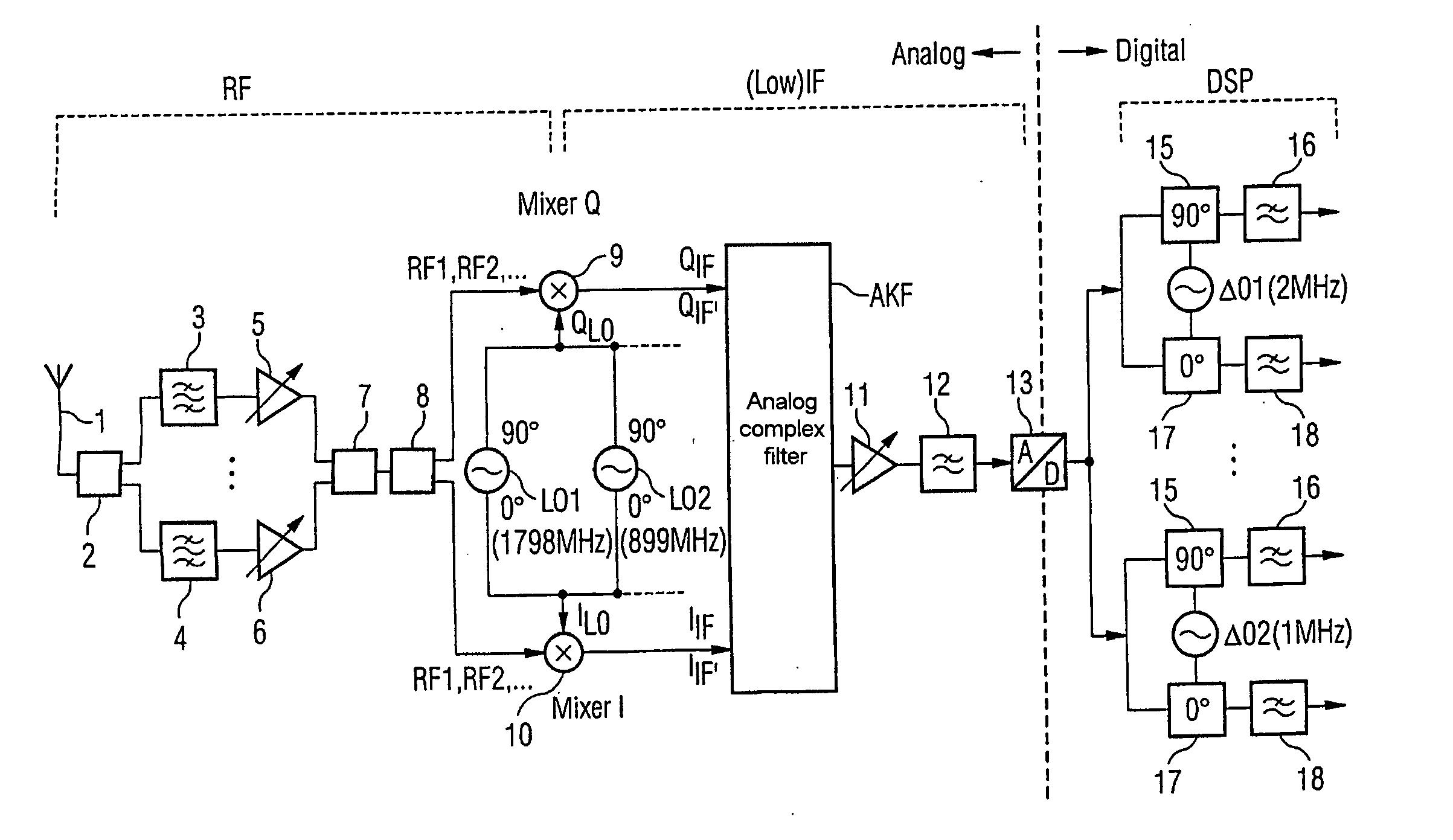
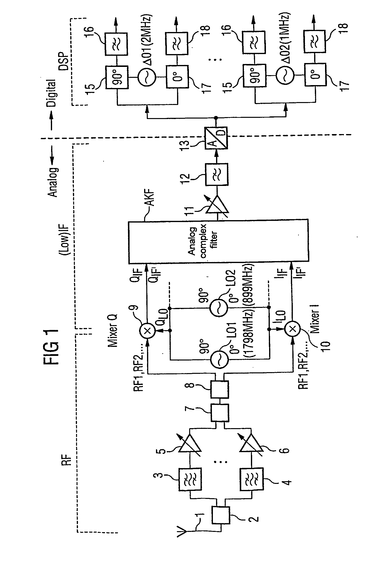
[0021]FIG. 1 shows a simplified block diagram of a multiband receiver for reception of two RF signals which are transmitted in a carrier frequency band at 1800 MHz and 900 MHz. An RF receiving part RF is used for reception of the RF signals via, for example, an antenna 1 and preprocessing via a preamplifier which includes the blocks 2 to 7. However, the antenna 1 may be replaced in the same way by a coaxial cable connection or some other connection for cable-based reception of RF signals. The preamplifier is used for so-called low noise amplification, and may, in principle also be omitted.

[0022] As is shown in FIG. 1, the input signal, which has at least two RF signals and is r...


PUM


Abstract

A multiband receiver and associated method are provided for simultaneous reception of a number of RF signals with partially different carrier frequencies. An RF / IF converter is provided with a number of local oscillators corresponding to a number of RF signals in order to produce L0 in phase components corresponding to the carrier frequencies and quadrature components; in addition to an in-phase mixer and a quadrature mixer for mixing the respective L0 in-phase and quadrature components with the RF signals in order to produce intermediate frequency signals with IF in-phse components and IF quadrature components. A complex fiber carries out complex filtering on the basis of the intermediate frequency signals in order to suppress reflected intermediate frequency signals.

Description

BACKGROUND OF THE INVENTION [0001] The present invention relates, generally, to a multiband receiver as well as to an associated method and, more particularly to a multiband receiver for simultaneous reception of multiband RF signals, some of which are at different carrier frequencies. [0002] The use of telecommunications networks using, for example, mobile radio systems has developed increasingly in recent years, leading to situations in which, in addition to earlier telecommunications radio networks, new networks, such as cellular networks, are often being added. [0003] As a consequence, a large number of different transmission standards are increasingly coexisting alongside one another; for example, digital and analog mobile telecommunications networks. By way of example, the GSM Standard (Global System for Mobile Communication), the DECT Standard (Digital European Cordless Telecommunication) and the UMTS Standard (Universal Mobile Telecommunication System) may be mentioned as di...

Claims


Application Information

Patent Timeline
Patent Type & Authority Applications(United States)
IPC IPC(8): H04B1/26H03D3/00H03D7/16H04B1/16H04J1/00
CPCH03D7/166H03D3/008H04B1/16
Inventor BURGT, CHIRON VAN DER
Owner GIGASET COMMUNICATIONS
Why Eureka
Try Eureka