Supercharge Your Innovation With Domain-Expert AI Agents!

Automotive engine accessory drive system

a technology for auto engines and drive systems, applied in valve drives, machines/engines, gearing, etc., can solve the problems waste of drive, and outstanding fuel economy problems, so as to boost the capability of the supercharger, reduce the loss of driving force to be given to the supercharger, and suppress the effect of deterioration of fuel economy of the vehicle engin

Inactive Publication Date: 2005-01-06
BANDO CHEM IND LTD
View PDF7 Cites 4 Cited by
  • Summary
  • Abstract
  • Description
  • Claims
  • Application Information

AI Technical Summary

Benefits of technology

[0010] The present invention has been made in view of the foregoing, and is directed to an automotive engine accessory drive system in which torque at a crankshaft is transmitted to accessories including a supercharger and an alternator. A principal object of the present invention is to use a light-weight, low-cost and power consumption-free belt drive system without any parts involving increases in weight, cost and power consumption, such as a solenoid-operated clutch, to prevent deterioration of fuel economy while ensuring that such accessories exhibit their abilities into full play.
[0011] To attain the above object, in the present invention, an input-side pulley is mounted on a crankshaft, an output-side flat pulley for normal cruise and another output-side flat pulley for low speed cruise or idling operation are mounted coaxially on a driven shaft of an engine accessory, and a flat belt entrained between the input-side pulley and the output-side flat pulley set is shifted in the belt widthwise direction to allow for the switching of the mode of power transmission from the vehicle engine to the engine accessory.

Problems solved by technology

This means that at low engine load, the amount of boost becomes excessive and the excess provides a loss of power to drive the supercharger 201, leading to deteriorated fuel economy.
In particular, under normal driving conditions, the engine is less likely to fall into full load conditions and therefore the fuel economy problem is outstanding.
On the other hand, when the engine rpm becomes high during actual cruise, such accessories are driven at an rpm higher than required (waste the drive power) thereby deteriorating fuel economy.
The above techniques, however, have a problem of increasing the weight, cost and power consumption of the drive system by an added solenoid-operated clutch or clutches.

Method used


Image

  • Automotive engine accessory drive system
  • Automotive engine accessory drive system
  • Automotive engine accessory drive system

Examples


embodiment 1

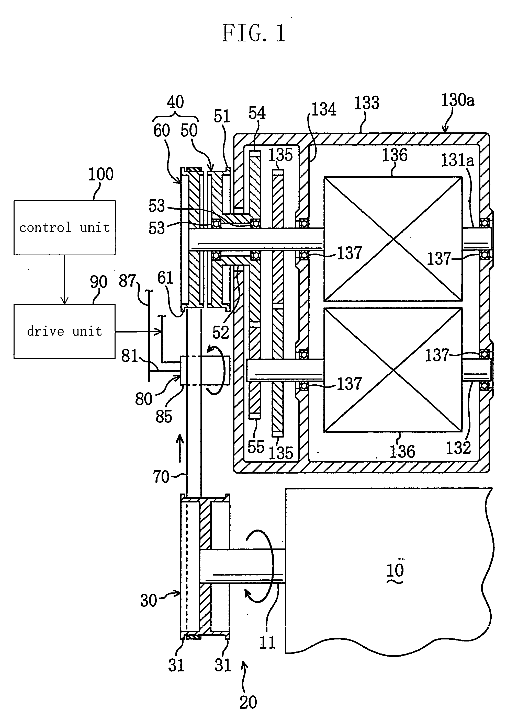
[0039]FIG. 1 shows the entire structure of a supercharger drive system according to a first embodiment of the present invention. This system is used to drive a supercharger 130a, which is an automotive engine accessory, by torque at a crankshaft 11 of an engine 10.

[0040] The supercharger 130a is of roots type that has a pair of lobed rotors 136 and 136 in a housing 133, and is disposed in an intake system leading from an air cleaner of the vehicle to an intake port of the engine 10, though they are not shown. One of the two rotors 136 and 136 is mounted on a first rotational shaft 131a for unitary rotation. The first rotational shaft 131a is a rotational shaft whose one end (left end in FIG. 1) extends outside the housing 133. The other rotor 136 is mounted on a second rotational shaft 132 for unitary rotation. The second rotational shaft 132 is placed in parallel with the first rotational shaft 131a. The rotational shafts 131a and 132 are each supported rotatably through two beari...

embodiment 2

[0061]FIG. 4 schematically shows the entire structure of a supercharger drive system according to a second embodiment of the present invention. Like parts as in the first embodiment are indicated by like reference numerals.

[0062] In the present embodiment, the output pulley unit 40 of the drive system 20 is composed of a driving pulley 50 and an idler pulley 60. The driving pulley 50 is a flat pulley for power transmission mounted on the first rotational shaft 131a of the supercharger 130a for unitary rotation. The idler pulley 60 is a flat pulley for drive disengagement placed on the supercharger 130a side (right side) of the driving pulley 50 relatively rotatably to the first rotational shaft 131a. When the driving pulley 50 rotates, the first rotational shaft 131a rotates at the same speed as the driving pulley 50 and is thereby driven into rotation at the same rpm as that of the engine 10. On the other hand, when the idler pulley 60 rotates, the first rotational shaft 131a ente...

embodiment 3

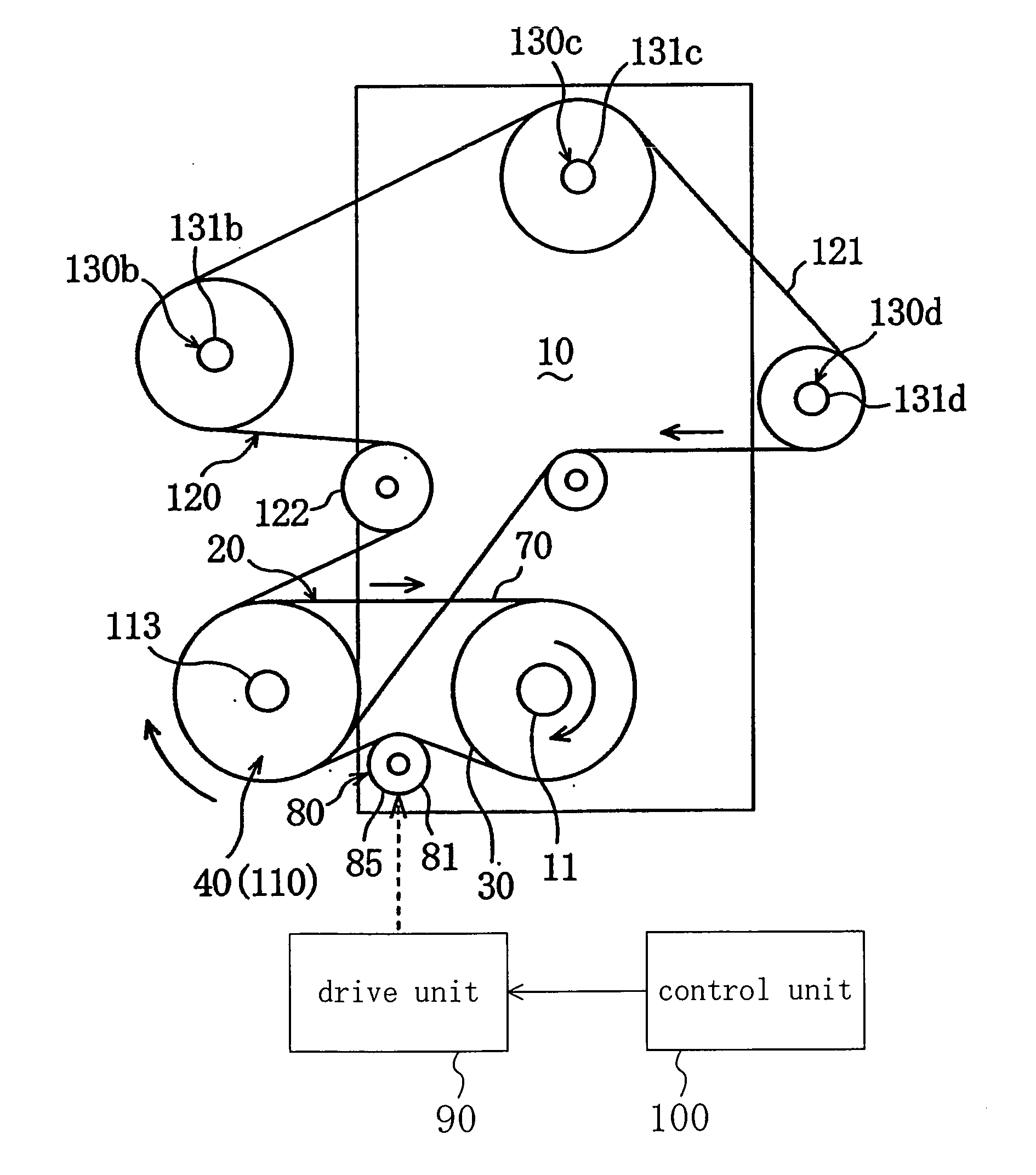
[0076]FIG. 7 schematically shows the layout of a vehicle engine accessory drive system according to a third embodiment of the present invention. In this embodiment, a serpentine belt drive system 120 as well as a flat belt drive system 20 are used. In the serpentine belt drive system 120, torque at the crankshaft 11 of the engine 10 is transmitted via a single power transmission belt to a plurality of engine accessories 130b to 130d.

[0077] First, description will be given of the serpentine belt drive system 120. This drive system 120 comprises a ribbed pulley 110 rotatably supported to the support shaft 113, a ribbed pulley 138b coupled unitarily rotatably to a rotational shaft 131b of a generator 130b which is an engine accessory, a ribbed pulley 138c coupled unitarily rotatably to a rotational shaft 131c of a power steering pump 130c which is an engine accessory, and a ribbed pulley 138d. coupled unitarily rotatably to a rotational shaft 131d of a compressor 130d for an automotiv...


PUM


Abstract

In a belt drive system 20 for transmitting torque at a crankshaft 11 of an automotive engine 10 to a supercharger (engine accessory) 130a, an output pulley unit 40 formed of a first flat pulley 50 and a second flat pulley 60 is coupled to the rotational shaft 131a of the supercharger 130a. A flat belt 70 entrained between the output pulley unit 40 and the crank pulley 30 of the crankshaft 11 is shifted from the first flat pulley 50 to the second flat pulley 60 or vice versa by a speed ratio selector 80. The rotational shaft 131a can thereby be driven into rotation with the switching between a high speed ratio during acceleration and a low speed ratio during constant speed cruise. As a result, the supercharger 130a can bring out its capability into full play without using parts involving increases in weight, cost and power consumption, such as a solenoid-operated clutch, and concurrently suppress the deterioration of fuel economy.

Description

BACKGROUND OF THE INVENTION [0001] (a) Field of the Invention [0002] This invention relates to drive systems for transmitting torque at the crankshaft of an automotive engine to engine accessories including a supercharger, a compressor for an automotive air conditioner, and a generator, and more particularly relates to measures for striking a balance between the acceleration and fuel consumption performances of an automotive engine. [0003] (b) Description of the Related Art [0004] An example of known drive systems for driving a supercharger using torque at an engine crankshaft is a continuous engagement type one in which as schematically shown in FIG. 10, a ribbed belt 204 is entrained between a crank pulley (not shown) as an input member coupled to the engine crankshaft and a ribbed pulley 203 as an output member coupled to a rotational shaft 202 of a supercharger 201. In this system, torque at the crankshaft is transmitted via the ribbed belt 204 to the rotational shaft 202 to rot...

Claims


Application Information

Patent Timeline
IPC IPC(8): F02B39/04F02B67/06F16H9/04F16H13/04
CPCF16H9/04F02B67/06
Inventor MIYATA, HIROFUMI
Owner BANDO CHEM IND LTD
Features
  • R&D
  • Intellectual Property
  • Life Sciences
  • Materials
  • Tech Scout
  • Unparalleled Data Quality
  • Higher Quality Content
  • 60% Fewer Hallucinations
Learn More