Method and apparatus for curving a catheter

a catheter and curving technology, applied in the field of catheters, can solve the problems of requiring some rigidity, the soft wall of the catheter needed to make the curve shape is often crushed or kinked during use, and the curve cannot be “set” outside of the body, so as to improve the positioning within the vascular system

a catheter and curving technology, applied in the field of catheters, can solve the problems of requiring some rigidity, the soft wall of the catheter needed to make the curve shape is often crushed or kinked during use, and the curve cannot be “set” outside of the body, so as to improve the positioning within the vascular system

US20050004555A1Inactive Publication Date: 2005-01-06VOLCANO CORP

Image

  • Method and apparatus for curving a catheter
  • Method and apparatus for curving a catheter
  • Method and apparatus for curving a catheter

Examples


first embodiment

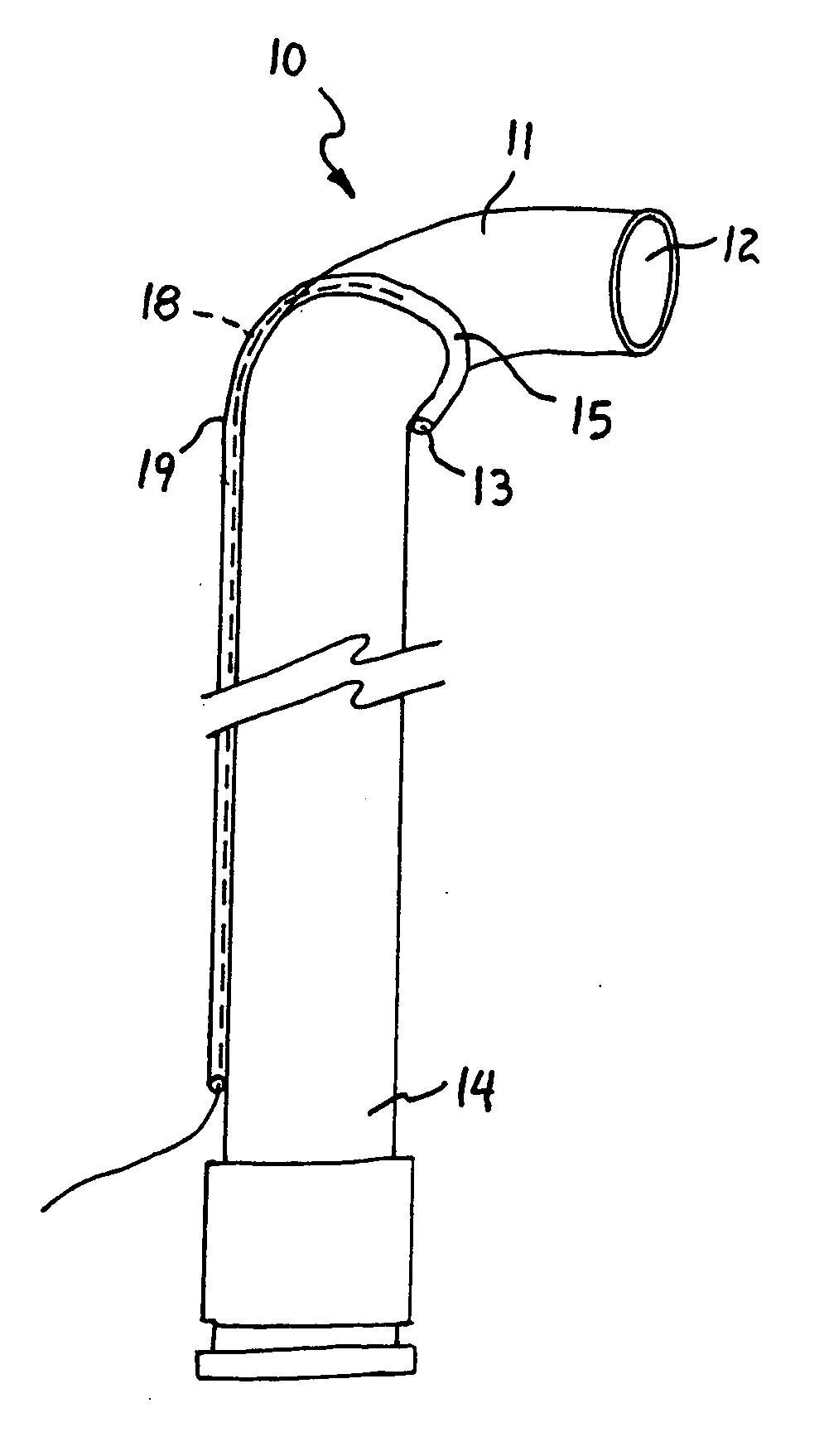
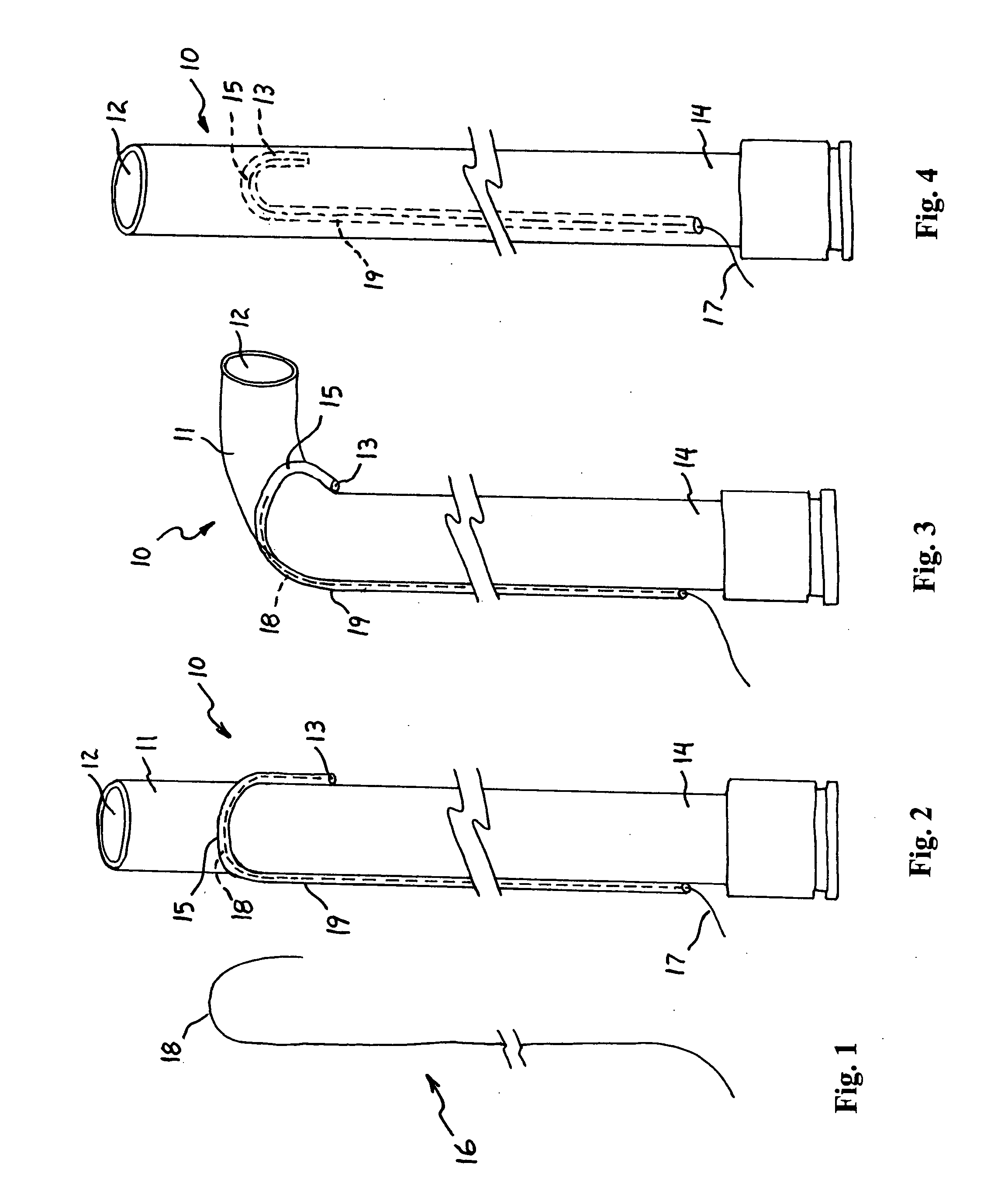
[0027] A catheter 10 having a deflectable distal tip 11 according to the present invention will be described with reference to FIGS. 1 to 4 of the drawings. The catheter 10 includes a primary lumen 12 as in conventional catheters, and a secondary lumen 13 that is either attached to the primary lumen 12 (as shown in FIGS. 2 and 3) or contained within the wall of the primary lumen 12 (as shown in FIG. 4). The secondary lumen 13 transverses the primary lumen 12 from the proximal end 14 of the catheter 10 to near the distal end 11 where it forms a partial loop configuration 15 (e.g., 180 degrees as shown in FIG. 2) and begins to track back toward the proximal end 14 of the catheter 10. Other shapes for the curved portion 15 of the secondary lumen 13 can also be used as long as the secondary lumen 13 has at least a portion near its distal end that is nonparallel to the primary lumen 12; i.e., the distal end of the secondary lumen 13 is curved, bent, or otherwise divergent from a path par...

second embodiment

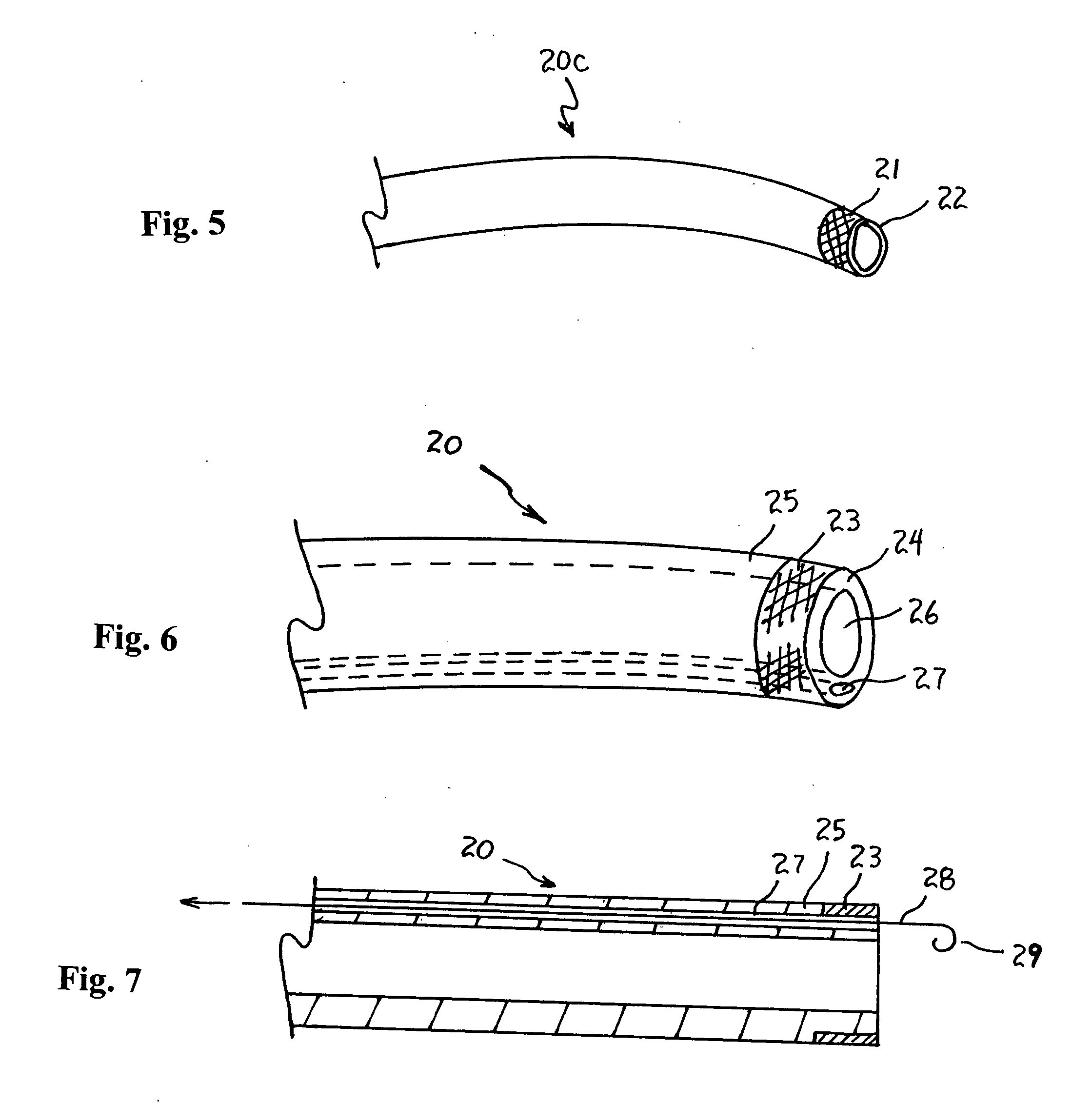
[0033] A catheter 20 according to the present invention will now be described with reference to FIGS. 5 to 10 of the drawings. A conventional catheter 20c having a marker band 21 at its distal end 22 is shown in FIG. 5. The marker band 21 is typically provided for visualization to facilitate positioning the distal end 22 of the catheter 20c within the anatomy.

[0034] The catheter 20 according to the second embodiment is shown in FIGS. 6 to 9. The catheter 20 has a marker band 23 at its distal end 24, which can be used for visualization similar to the marker band 21 in the conventional catheter 20c of FIG. 5. The marker band 23 is formed of a hard polymer, while the other part 25 near the distal end of the catheter 20 is formed of a soft, flexible polymer material. The marker band 23 does not affect the overall flexibility of the catheter 20 because it only affects the catheter shaft for a very short region (i.e., the catheter 20 is stiff only where the marker band 23 is located).

[00...


PUM


Abstract

An apparatus and method for curving a catheter after deployment include a catheter having a primary lumen, a secondary lumen, and a resilient fiber contained within the secondary lumen. The resilient fiber and the secondary lumen have corresponding, preformed curve shapes when the catheter is in a straight, unstressed condition. The resilient fiber is slidable within the secondary lumen to create a desired curve shape in the catheter as the curved portion of the resilient fiber slides into an originally straight portion of the secondary lumen. In another embodiment, the preformed curve shape of the resilient fiber is held in a straight condition within a stiff, marker ring segment of the catheter until after the catheter is deployed. Once deployed, the resilient fiber is slid out of the marker ring segment, and the preformed curve shape of the resilient fiber creates a corresponding curve shape in the catheter.

Description

RELATED APPLICATIONS [0001] This application claims the benefit of the Applicant's provisional patent Application No. 60 / 483,867 filed on Jun. 25, 2003, and also relates to the subject matter of Applicant's copending U.S. application Ser. No. 10 / 167,718 filed on Jun. 11, 2002, which is hereby incorporated by reference.BACKGROUND OF THE INVENTION [0002] 1. Field of the Invention [0003] The present invention relates generally to catheters and, in particular, to catheters that can be curved or bent at their distal ends or other selected locations, and methods for making and deploying such catheters. [0004] 2. Description of the Related Art [0005] Catheters frequently have “preset” curves in them to enhance the physician's ability to introduce the catheter to the desired location. Usually, this curve is “set” in the catheter by first bending the catheter to the desired shape, then applying heat to the catheter while in this curved state, and then allowing the catheter to cool while stil...

Claims


Application Information

Patent Timeline
06 Jan 2005
Publication
US20050004555A1
IPC
A61M25/01
CPC
A61M25/0152
Inventors
PURSLEY, MATT D.