Audibility enhancement

a technology of enhancement and enhancement, applied in the field ofaudibility enhancement, can solve the problem of high near-end speech level

Active Publication Date: 2005-01-06
TELEFON AB LM ERICSSON (PUBL)
View PDF5 Cites 109 Cited by
  • Summary
  • Abstract
  • Description
  • Claims
  • Application Information

AI Technical Summary

Problems solved by technology

This solution is based on the assumptions that if the terminal equipment at the near-end side is designed to operate in a noisy environment, it is likely that the near-end user will have a speech level close to the nominal level Similarly, if...

Method used


Image

  • Audibility enhancement
  • Audibility enhancement
  • Audibility enhancement

Examples


Embodiment Construction

In the following description the same reference designations will be used for the same or similar elements throughout the figures of the drawings. Furthermore, in order to avoid cluttering of the figures, only elements necessary to explain the invention are shown in the drawings. Thus, elements such as radio equipment, speech coders / decoders, etc. have been omitted.

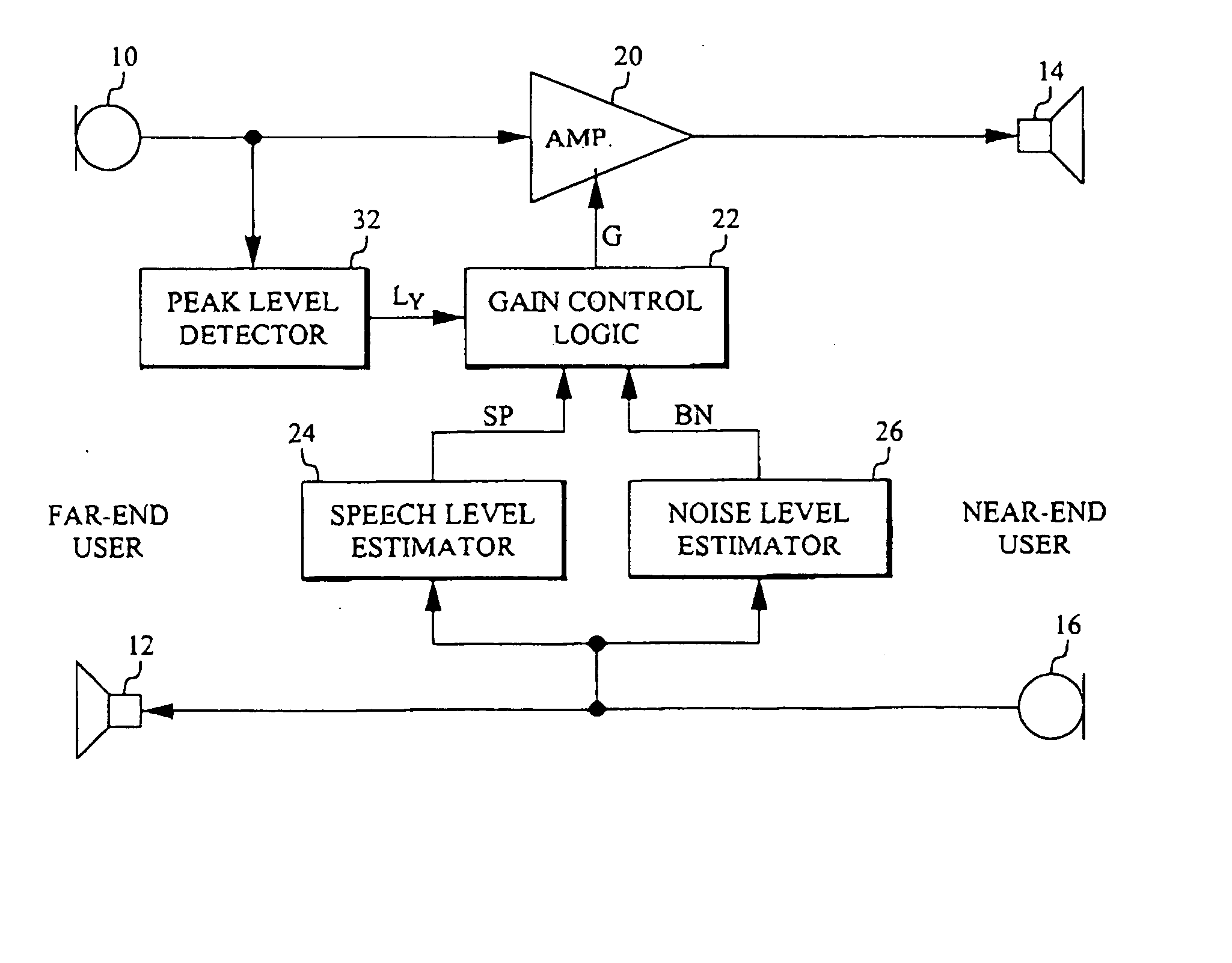
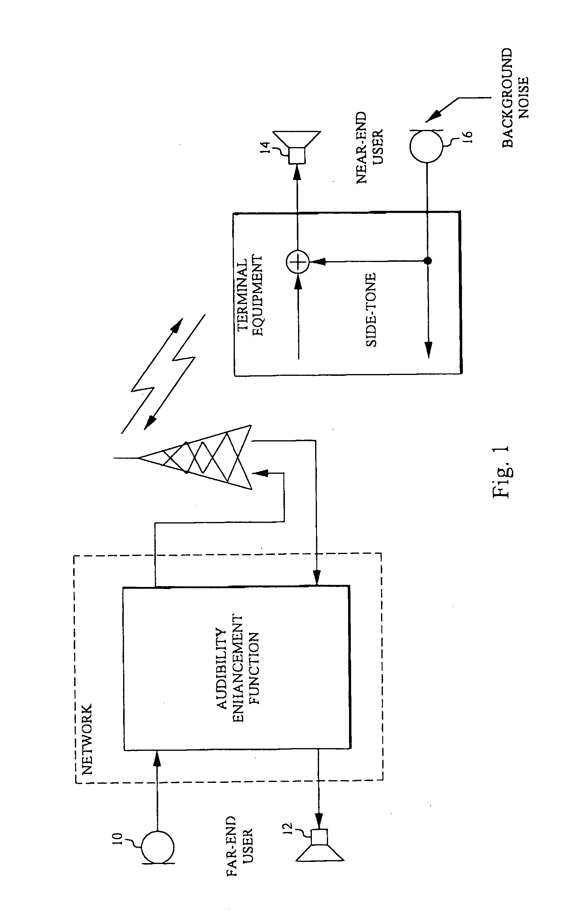
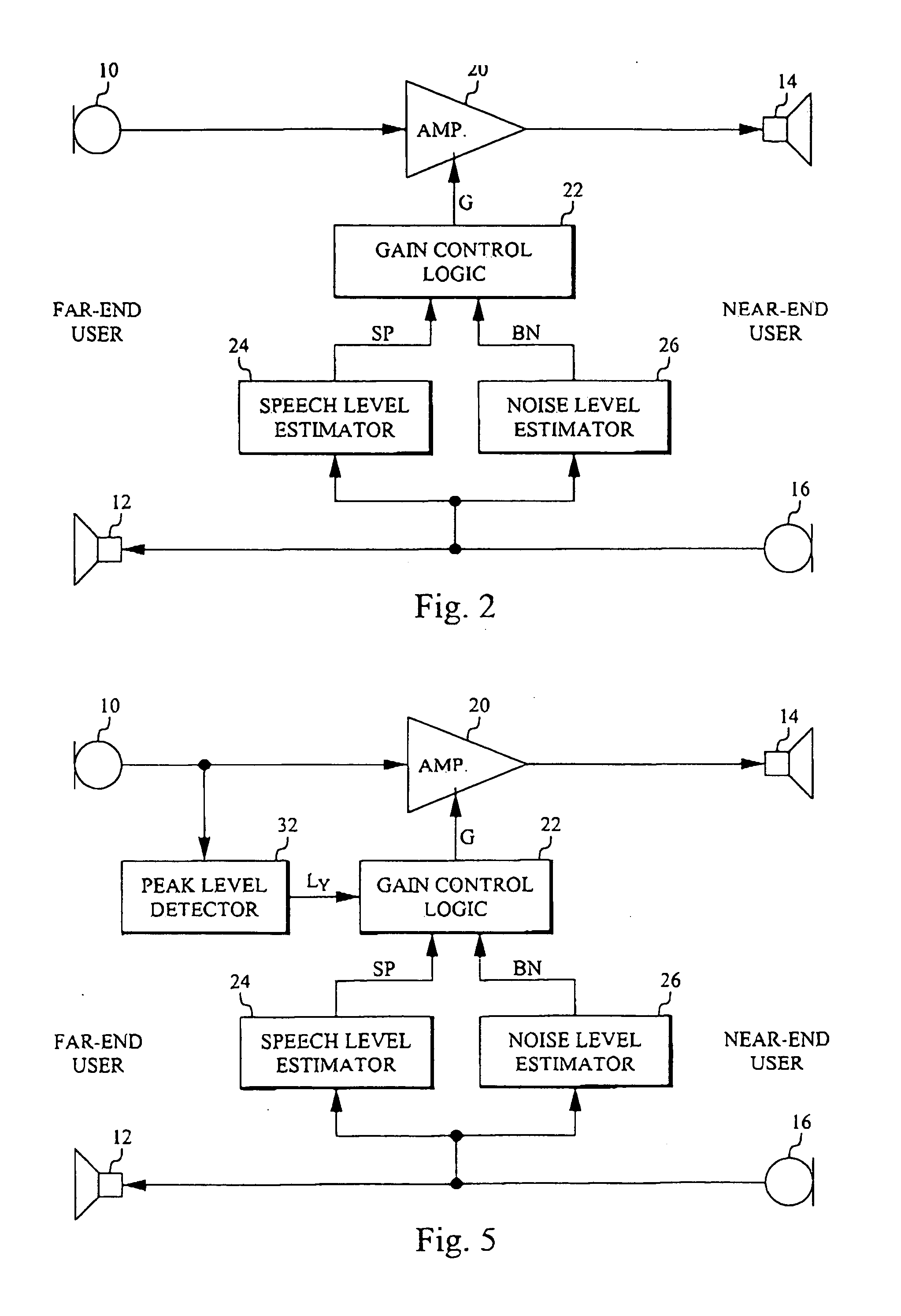
The problem at hand and the terminology used in this document is described in FIG. 1. A far-end or sending user provided with a telephone set having a microphone 10 and a loudspeaker 12 sends speech signals over a telephone network to a near-end or receiving user provided with a terminal having a loudspeaker 14 and a microphone 16. The terminal equipment at the near-end picks up near-end speech and near-end background noise in microphone 16. In some embodiments of the terminal equipment a portion of this noise is added to the received far-end signal as a side-tone before the combined signal reaches near-end loudspeaker...


PUM


Abstract

An apparatus for enhancing audibility of a far-end speech signal from a far-end user to a near-end user in a telephony system includes a near-end background noise signal level estimator (26) at the near-end user. A near-end speech signal level estimator (24) is also provided at the near-end user. A gain control logic (22) determines a gain (G) for amplification of the far-end speech signal based on both estimated speech and background noise signal levels.

Description

TECHNICAL FIELD This invention relates to audibility enhancement by controlling the level of the loudspeaker signal in a terminal, for example a mobile handset, in a telephone system when used in a noisy environment. BACKGROUND When making a telephone call in a noisy environment the audibility of the far-end speech may at times be low, since the loudspeaker signal may be drowned by the background noise at the near-end. At such occasions, it would be beneficial to increase the loudness of the far-end speech signal in order to improve the audibility. Most mobile terminals used today include a manual volume control that can be used for increasing the loudspeaker volume. However, this may not always solve the problem of enhancing the audibility, and that mainly depends on the so-called side-tone that most often is included in a mobile terminal. The side-tone adds a portion of the talkers voice to the loudspeaker in order to make the terminal sound “more alive”. Typically, the side-to...

Claims


Application Information

Patent Timeline
IPC IPC(8): G10L19/14H03G3/32H04M1/60H04M1/724H04M9/08
CPCH03G3/32H04M9/08H04M1/72519H04M1/6016H04M1/724
Inventor TRUMP, TONUERIKSSON, ANDERS
Owner TELEFON AB LM ERICSSON (PUBL)
Why Eureka
Try Eureka