Apparatus for engraving images and its adaptor

a technology of engraving image and adaptor, which is applied in the field of engraving image adaptor, can solve the problems of increasing the burden of users, taking a long time and costing a lot to develop software and data, and affecting the quality of engraving images,

Inactive Publication Date: 2005-01-13
SEMCO INT LTD
View PDF12 Cites 2 Cited by
  • Summary
  • Abstract
  • Description
  • Claims
  • Application Information

AI Technical Summary

Benefits of technology

[0015] A principal object of this invention is to provide an apparatus for engraving images which comprises a personal computer, a controller, an X-axis pulse motor driver, a Y-axis pulse motor driver, an X-axis pulse motor, a tilt motor driver, a Z-axis head motor having a minute ΔY-axis driver, a stylus and a vacuum pump whereby photographs of faces, addresses, names, autographs, the images for engraving information identifying one's identity, the images from a digital camera, scanner or other information taken from a computer through a network can be automatically and correctly engraved on identification cards such as passports, drivers' licenses, employee certificates or credit cards.

Problems solved by technology

In addition, it takes a long time and costs much to develop software and data, and it is also necessary for a user to get used to the method of using the conventional engraving apparatus, thus increasing burden of the user and making it difficult to transmit, edit and compress the data and causing much confusion and trouble.
The biggest disadvantage of the conventional engraving apparatus is that when making a personal card, it requres to make engraving apparatus file data such as a face picture, address, name, or autograph of one person independently and to designate all of the files and to collect and integrate the data.
Further, it is likely that vibrations of an engraving head of the conventional engraving apparatus oscillate the engraving apparatus itself to cause incorrect engraving.

Method used


Image

  • Apparatus for engraving images and its adaptor
  • Apparatus for engraving images and its adaptor
  • Apparatus for engraving images and its adaptor

Examples


Embodiment Construction

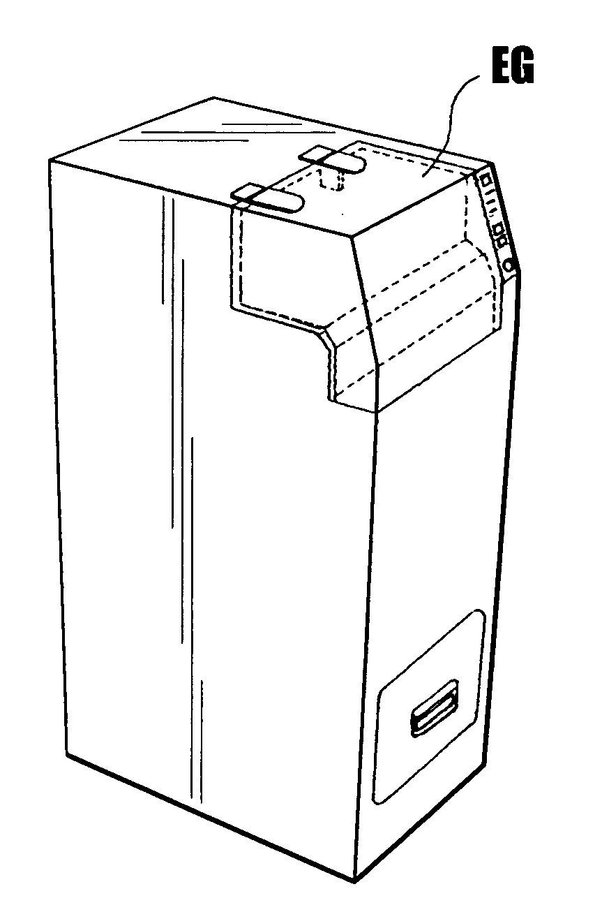
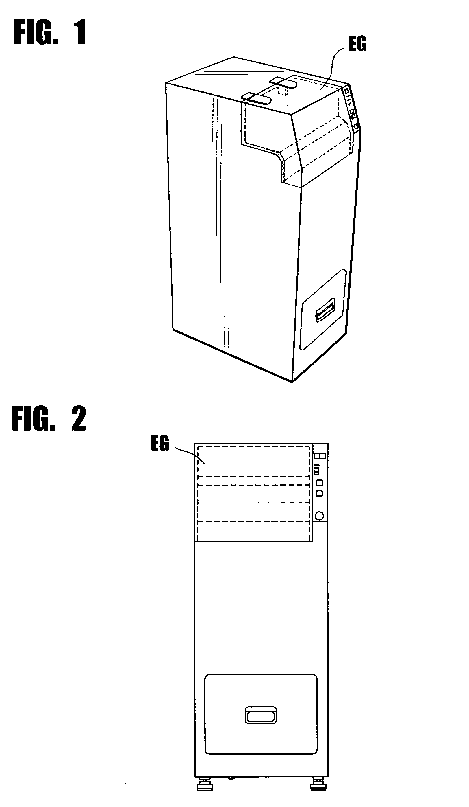
[0034] Referring to the accompanying drawings in which like numerals designate the like parts throughout the several views thereof, this invention will be explained to an example of an apparatus EG for engraving images is connected to a personal computer PC.

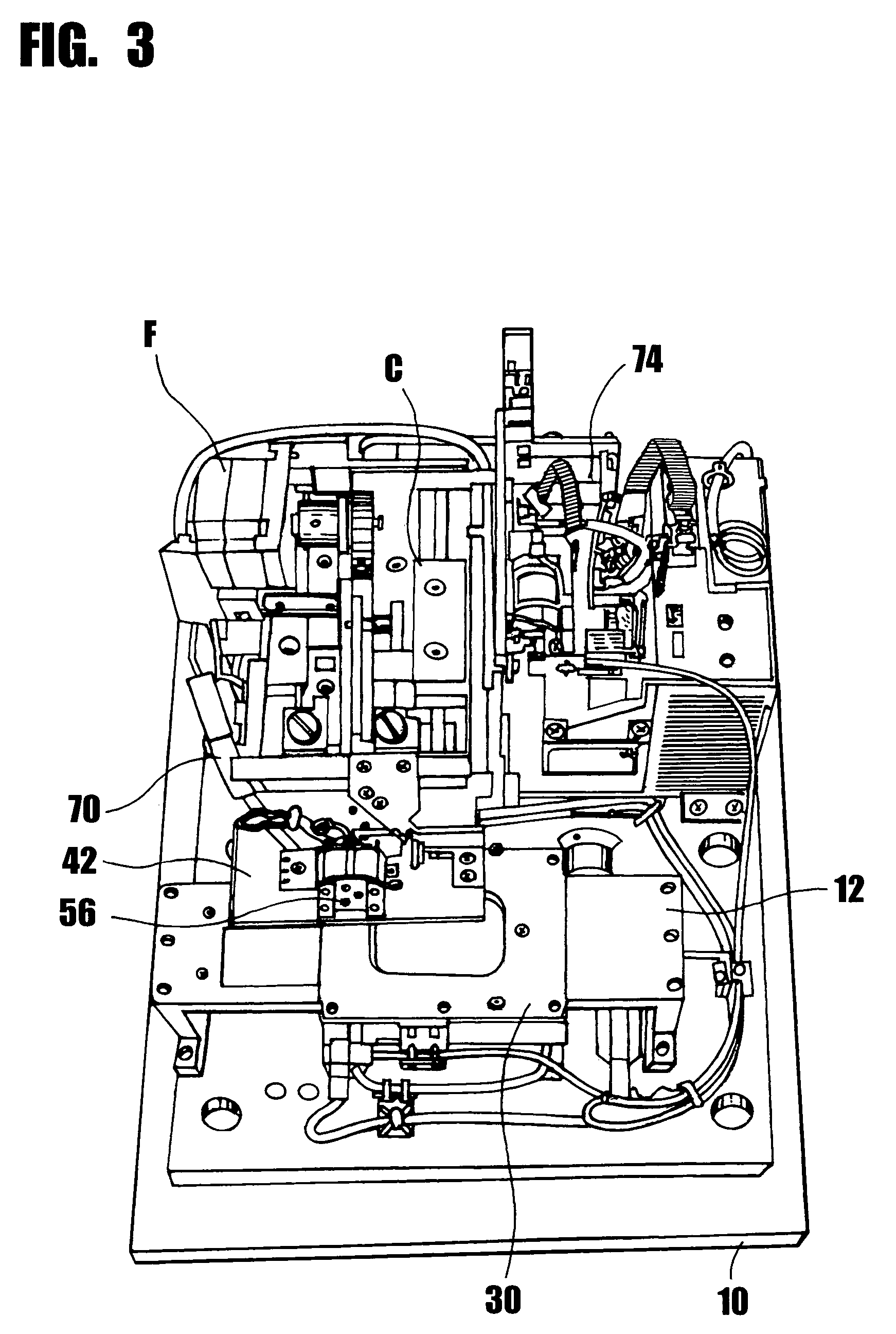
[0035] As particularly shown in FIGS. 2-6, the apparatus EG comprises a base plate 10 having a given thickness and a width, on which a Π-shaped driving stand 12 having a pair of legs 12a, 12a is rigidly mounted.

[0036] An opening (not shown) is provided through a central portion of the leg 12a, and a pair of bearings 18, 18, each having an opening (not shown), are made independently.

[0037] Both end portions of a spindle 14 is penetrated through the openings of the bearings 18, 18 and the openings of the legs 12a, 12a with a pair of coil springs 16, 16, each being located between the leg 12a and the bearing 18 respectively.

[0038] It should be appreciated that the spindle 14 is mounted to extend horizontally and in parallel with...


PUM

PropertyMeasurementUnit
widthaaaaaaaaaa
thicknessaaaaaaaaaa
widthaaaaaaaaaa

Abstract

An apparatus for engraving images on a passport, credit card, identification card, or the like, and its adaptor for use in the apparatus, the apparatus comprising a personal computer, a controller, a vibration-preventing unit, an X axis pulse motor driver, a Y axis pulse motor driver, an X axis pulse motor., a tilt motor driver, a Z axis head motor having a minute ΔY axis driver, a stylus and a vacuum pump whereby photographs of faces, addresses, names, autographs, the images for engraving information identifying one's identity, the images from a digital camera, scanner or other information taken from a computer through a network can be automatically and correctly engraved on identification cards such as passports, drivers' licenses, employee certificates or credit cards.

Description

BACKGROUND OF THE INVENTION [0001] 1. Field of the Invention [0002] This invention relates to an apparatus for engraving images and its adaptor, and more particularly, an apparatus for engraving images such as photographs of faces, addresses, names, autographs, the images for engraving information identifying one's identity, the images from a digital camera, scanner or other information taken from a computer through a network on identification cards such as passports, drivers' licenses, employee certificates or credit cards, and its adaptor. [0003] 2. Description of the Prior Art [0004] There have been proposed various engraving apparatuses (for example, U.S. Pat. No. 5,232,231, Japanese Patent publication Nos. 115676 / 1989, No. 201762 / 1988). [0005] According to the conventional apparatus for engraving images on the passports, driver's licenses, employee certificates or credit cards, a magnetic layer is coated on a surface of a plastic card or synthetic paper, and if necessary, a giv...

Claims


Application Information

Patent Timeline
Patent Type & Authority Applications(United States)
IPC IPC(8): B42D15/10B44B1/00B44B1/06B44B3/00B44B5/00
CPCB25B11/005B44B3/009Y10T409/302408B44B3/065Y10T409/301344B44B3/02
Inventor HOSHIYAMA, YUICHI
Owner SEMCO INT LTD
Why Eureka
Try Eureka