Window box and mounting system

a window box and mounting system technology, applied in the field of windows, can solve the problems of difficult installation, deterioration of window boxes, and system relying on gravity force, and achieve the effect of strong and easy installation

Inactive Publication Date: 2005-01-13
PERKINS DARCIE WOODRUFF
View PDF17 Cites 1 Cited by
  • Summary
  • Abstract
  • Description
  • Claims
  • Application Information

AI Technical Summary

Benefits of technology

[0019] The window box has been modified from the prior art in that it has support bars located on the bottom back of the window box and includes a mounting bar fitted to match the length of the window box. Together, the modified window box design and mounting bar from the basic unit will not slant or pull off away from the wall and the mounting system will be hidden from view when the window box is installed and it offers a strong and easy installation of the mounting bar and allows the window box to be installed without the use of tools and enables window boxes to be used on buildings with varies types of storm shutter systems.

Problems solved by technology

First, window boxes often leave installation up to the user or inhabitant of the building or can be difficult to install.
Others may require the use of visible brackets, or do not securely attach to the building but rather rest on the above mentioned brackets.
Systems that rely on the force of gravity could be hazardous in severe weather or when the window box is left empty or becomes light in weight due to insufficlient watering.
Secondly, window boxes often deteriorate in harsh weather conditions.
They may not be attached secure enough to withstand strong winds, are often made of materials that will rot or rust.
Thirdly, window boxes can be difficult to maintain in inclement weather or seasonal use.
Fourthly, no prior art was found to be designed for use in conjunction with storm shutter systems.
Although window boxes are commonly found commercially, no prior art offers installment solutions and the flexibility needed for seasonal use or in tandem with some storm shutter systems.
Often, the depth of the window box makes using drills or other power tools difficult or impossible to use.
These window box designs lack a solution for installation, but rather leave it up to the user to determine a mounting method.
On structures with some storm shutter systems, the permanence of the direct installation makes these window boxes incompatible.
Brackets that are left unused are aesthetically undesirable, but could also pose potential hazards to humans in areas where people congregate.
Additionally, on structures with storm shutter systems, brackets may need to be removed before the storm shutters can be installed.
In addition, not all windows have a window sill substantial enough to support said mounting systems.
Window boxes with mounting systems that rely on a sill as support, severely limit the choice where a user can mount a window box, and often interfere with some storm shutter systems.
As stated above, brackets that require a sill severely limit the placement of the window box.
However, depending on the style of the window box, the window box may or may not be secured to the brackets.
Additionally with Cougar, the brackets are visible with the window box installed and with the window box removed, the brackets would stick out from the wall causing problems for storm shutters and potential hazards for humans.

Method used


Image

  • Window box and mounting system
  • Window box and mounting system
  • Window box and mounting system

Examples


Embodiment Construction

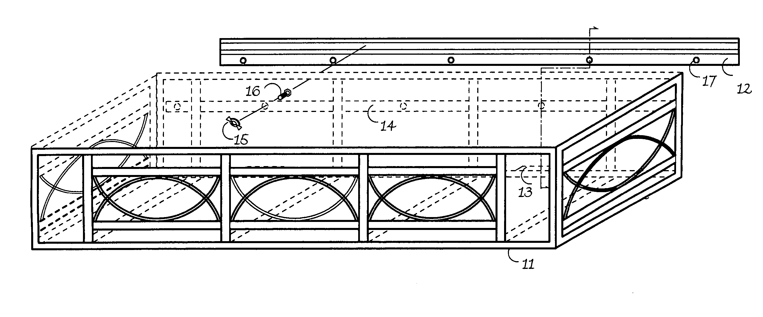
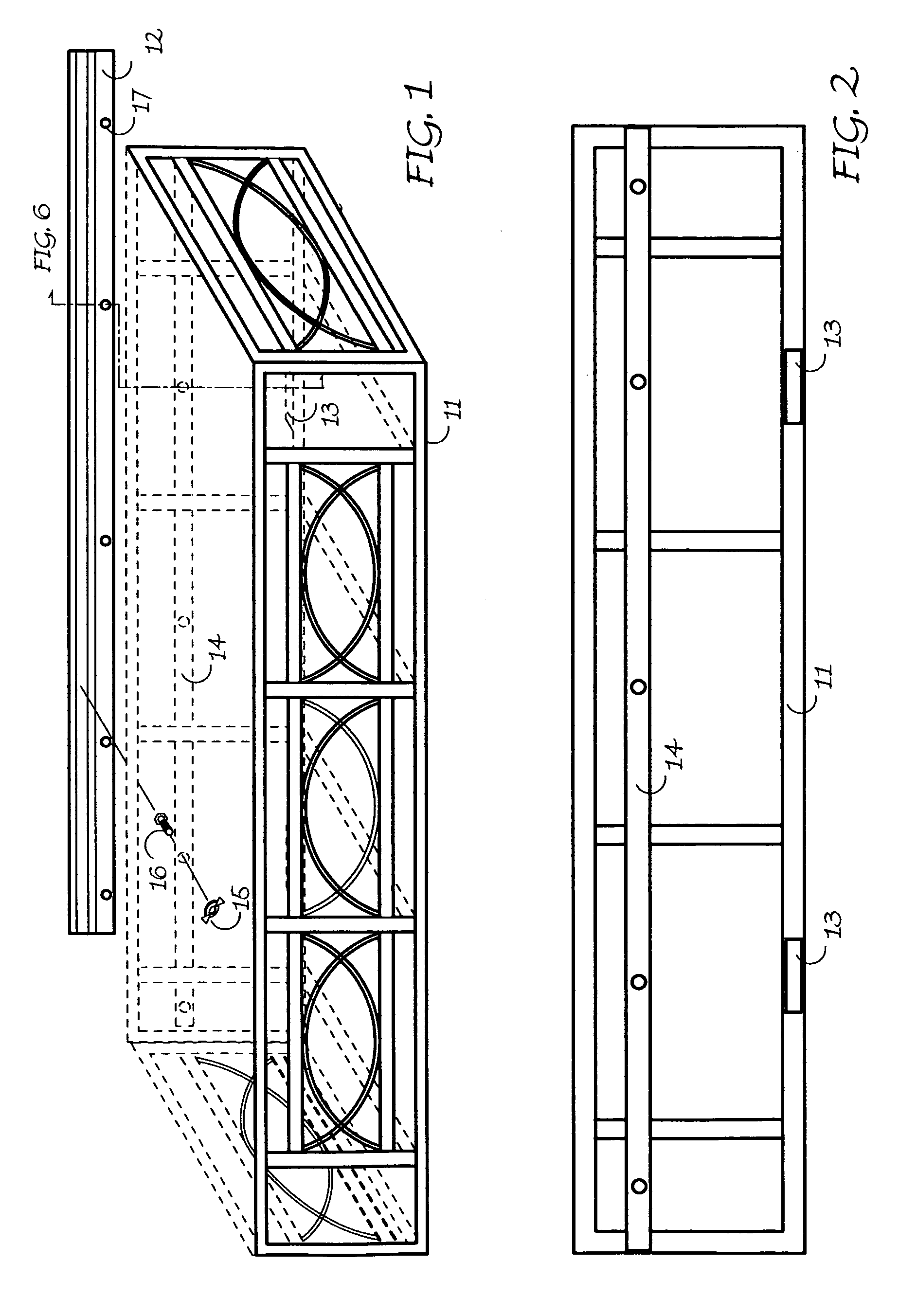
[0026]FIG. 1 is a perspective view taken from the user's right side of the window box 11 and an exploded view of the complete mounting system. The window box 11 in this Fig. is 45 inches in length, however, all dimensions of the window box are for illustrative purposes only, as it is the intention that this mounting system can be used with any size window box or object. The window box 11 can be made of aluminum, although, the material is not the object of this invention as any other material could be used to provide a similar utility. The advantages and reasons for aluminum in the described window box design box 11 is that aluminum does not rust.

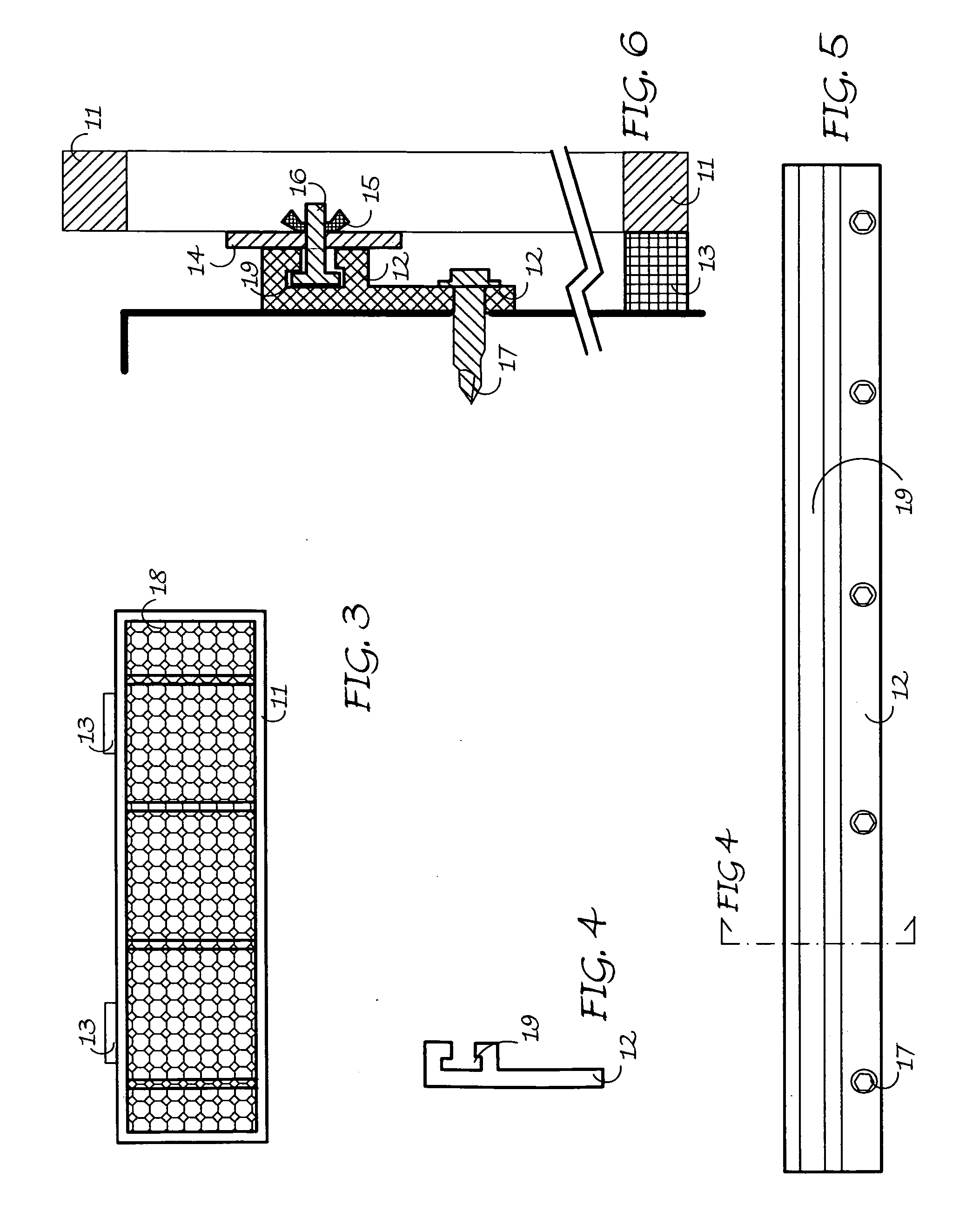
[0027]FIG. 1 illustrates that a mounting bar 12 (made of aluminum) is attached using conventional hardware (e.g. TEK screw in masonry) and the window box 11 is then attached to the mounting bar 12 using stainless steel bolts 16 and wing nuts 15 at regular intervals. Also showing (but better illustrated in FIGS. 2 & 6) are two support bars 1...


PUM


Abstract

A window box is designed to be compatible with a specific mounting bar to provide a very secure, yet versatile installation. When installed, the mounting bar is completely from view. When the window box is not installed, the mounting bar remains flush with the wall it is mounted upon and is nor obtrusive. The window box is attached to the secure mounting bar using bolts and wing nuts, thereby allowing users to easily and quickly install and / or remove the window box. The flush design of the mounting bar and the ability to remove the window box in a timely fashion without the use of tools allows the window box and the mounting system to be compatible with many hurricane shutter systems.

Description

CROSS REFERENCE TO RELATED APPLICATIONS [0001] This application is a Continuation of a Provisional Application No. 60 / 486,689 having a filing date of Jul. 11, 2003.STATEMENT REGARDING FED SPONSORED R & D [0002] (none) BACKGROUND OF THE INVENTION [0003] The invention relates to window boxes and the manner in which they are mounted to a structure. Window boxes, having greenery and / or flowers placed therein, are a significant asset to a building's appearance, yet they are not commonly used for four reasons: [0004] First, window boxes often leave installation up to the user or inhabitant of the building or can be difficult to install. Others may require the use of visible brackets, or do not securely attach to the building but rather rest on the above mentioned brackets. Systems that rely on the force of gravity could be hazardous in severe weather or when the window box is left empty or becomes light in weight due to insufficlient watering. [0005] Secondly, window boxes often deteriora...

Claims


Application Information

Patent Timeline
Patent Type & Authority Applications(United States)
IPC IPC(8): A47G7/04A47H27/00G06F7/00H04L12/24
CPCA47H27/00A47G7/044
Inventor PERKINS, DARCIE WOODRUFF
Owner PERKINS DARCIE WOODRUFF
Why Eureka
Try Eureka